
The term “ground” is one of the most frequently used words in electronics, and it’s also one of its most-often misused and misunderstood terms. Fortunately, in many cases of misuse, the engineers using it know what it actually being referred to, and are able to translate it internally and so avoid negative consequences.
However, there are many situations where improper or too-casual use of the term leads to miscommunication. Further, such sloppy use in terminology can also lead to sloppiness in design, as there are many types of “grounds” and some that really aren’t ground at all.
- What is “Earth” ground?
Earth ground is historically the first ground that people involved with electricity used (before electronics as well know it existed). It is the connection of a circuit, system, rack, chassis, or household AC wiring to the Earth via a low-resistance connection. This is often, though not exclusively, done through the ground connection of the three-wire AC plug/receptacle, which in turn connects to a grounding structure of rods driven into the Earth. The specific configuration of rods depends on the local resistivity of the soil and moisture conditions and the local electrical code. The correct symbol for Earth ground is shown in Figure 1.

- Why use Earth for safety?
Dangerous conditions which can affect life occur when excess current flows through the person, and current is “driven” by a sufficiently high voltage, such as the AC line. Therefore, one way to prevent this current flow is to provide an alternate path of much-lower resistance; keep in mind that current will self-adjust to flow through a lower-resistance path which is in parallel with a path having a higher resistance.
Since a person has resistance of hundreds to thousands of ohms, while the Earth-ground path resistance is on the order of ohms or less. If a wiring short-circuit occurs and the chassis becomes hot (electrified), the AC-line current will flow through this ground to Earth rather than through the person. Earth acts as a near-infinite source and sink for undesired excess currents. The Earth ground is sometimes called a safety ground.
- Do all AC-operated products need an Earth ground?
No, not all appliances and consumer products need to have a safety-related Earth ground and three-wire cord. Many power tools and even low-end appliances such as hairdryers are double-insulated, meaning that two or even three internal failures would have to occur to make their fully insulated, plastic case become “live”. Therefore, the various codes do not require an Earth-ground connection for these products. This is a good thing, since many three-wire AC-line connections have a faulty or nonexistent connection to Earth ground due to improper installation, a broken connection, or improper use with older outlets of a 3-wire/2-wire adapter.
- What is a chassis ground?
Chassis ground means just that: the metal chassis or enclosure is a common connection point for all power and signal “grounds” in a design. In most cases, for AC-line operated devices, the chassis ground, Figure 2, must be connected to Earth ground for safety. However, there are some specific cases where it must not be connected to Earth ground, due to unique application or code requirements. Like Earth ground, chassis ground is sometimes called the safety ground—another source of possible confusion.
Since many of today’s products have non-metallic cases or enclosures, the term “chassis ground” should not be assumed to connect to Earth ground for safety. Also, many non-AC line devices and systems have no possibility of connection to Earth ground (such as an airplane or car), even if they are in metal enclosures. In these cases, chassis ground usually a common connection point for all the so-called grounds within the system.
- What other grounds are in a circuit?
In a typical design, there may be power-related grounds for both AC-line sourced power as well as DC power, whether that DC is derived from the AC line or from batteries and associated DC/DC regulators. There are also what are often referred to as grounds for the various analog and digital functional blocks and signals within the device.
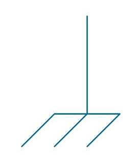
None of these is necessarily a “ground” in the sense of having an eventual connection to Earth ground. A much better and more descriptive term for these grounds is “common” as represented by the symbol of Figure 3. If the design is AC-line powered, the common connection is eventually connected to chassis ground and then to Earth ground in most (but not all) cases.

In many designs, there are two, three, or more commons. There may be one common for each power supply subsystem, and one each for various digital subsystems and analog subsystems; in fact, it is not unusual to have multiple commons for analog and digital sides. In general, all these commons should be connected together at a single point, called a star connection, for signal and power integrity. Standard practice is to differentiate among these independent commons by putting a number within their respective triangles.
- Can Earth ground be used for RF signals?
Yes, it can, but it is usually a poor path for RF signals. The reason is that while conductors to Earth ground may be heavy, low-gauge wires and rods (required by various safety codes), and so present a low impedance to DC and low-frequency AC, they usually have fairly high parasitic inductance and capacitance and so present a high impedance to higher-frequency signals. Designing and implementing good RF signal grounds is a skill and art.
Given all these grounds and commons, how should they be connected to each other? That’s the subject of part 2 of this FAQ.