Antennas based on fractal mathematics offer some significant advantages but also some controversy.
The first part of this article looked at the basic concept and history of fractals. This part looks at the relationship between fractals and antennas.
Q: All this fractal discussion is interesting, but what does it have to do with antennas?
A: A fractal antenna is an antenna that uses a fractal, self-similar design to maximize the effective length or increase the perimeter (on inside sections or the outer structure) of material that can receive or transmit electromagnetic radiation within a given total surface area or volume.
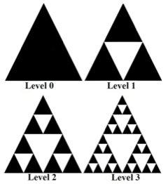
Figure 1. The Sierpinski gasket is a triangle-based fractal design that breaks the original triangle into ever-smaller triangles; shown are the first four stages but most designs use six, seven, or more stages (Image: ResearchGate).
Q: What makes them special?
A: Fractal antennas have space-filling properties that can be used to miniaturize classic antenna elements and overcome some of the limitations of small antennas. In many fractal-based antennas, the fractal structure provides a virtual combination of capacitors and inductors, so the antenna has many resonances which vary according to the fractal design. The current on the structure has a complex arrangement caused by inductance and self-capacitance. Due to this reactive loading, the antenna elements can be compacted into a smaller space even if they are electrically long.
Q: What’s an example of a fractal antenna?
A: The Sierpinski gasket is a type of deterministic fractal and is used in some smartphones (Figure 1).
Q: What does a real fractal antenna look like?
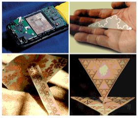
A: As with all antennas, they can take many forms (Figure 2).
Q: Are fractal antennas restricted to PC boards and other small-size situations?
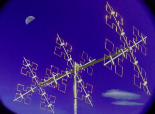
A: No, they can be built fairly large and mast-mounted (Figure 3).
Q: How did these fractal-based antennas come about?
A: It’s an interesting and fully documented story. Mandelbrot gave a paper on the landscapes of an imaginary planet at the 99th Colloquium of the International Astronomical Union, held in Balaton, Hungary in June of 1987. Also giving a paper at the conference was IEEE member and radio astronomer Prof. Nathan Cohen of Boston University.
Cohen was a ham radio operator, and he wondered how an antenna shaped according to fractal geometry would work. Cohen was working with a 2-meter FM, meaning that a conventional antenna would need an element about one meter long and thus be quite visible outside his apartment (his landlord did not allow these protuberances). Thinking back to Mandelbrot’s lecture and book, he bent an antenna into a fractal shape and found that his radio came in much clearer than before.
Cohen made his fractal microstrip antenna out of aluminum foil, glue, and construction paper using the pagoda motif and attached it to the railing of his apartment. It was about six inches square, and he found that it worked very well.
Q: Is that the end of the fractal-as-antenna story?
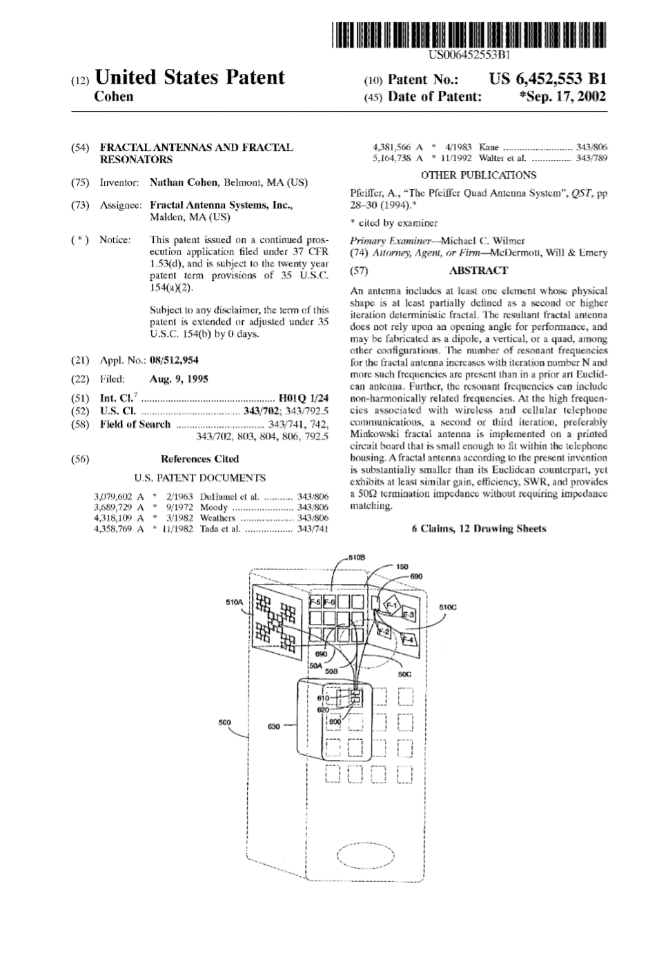
A: Not at all; it’s really the beginning. Cohen subsequently founded Fractal Antenna Systems and filed a US Patent 6,452,553 in August of 1995 for the fractal antenna, which was granted in 2002 (Figure 4).
Q: Where are fractal antennas used?
A: They are used in some smartphones, RFID tags, vehicular radar, and collision-avoidance systems. They reduce the scattering of the signal and enhance the radar reflection of highway tags. They are favored when wideband or multiband operation is needed, as is the case in smartphones today.
Q: What can be said about their characteristics?
A: They increase realizable gain in small sizes. This is because they can produce multiple current maxima, such as on a fractal perimeter, in a highly compact area. Constructive interference can therefore occur in structures that are far smaller than a one-quarter wavelength, where other antennas suffer.
Q: It seems as if fractal antennas are the answer to many antenna issues — is this the case?
A: Actually, fractal antennas are somewhat controversial. On one side, they are in widespread use in many products serving diverse applications due to their favorable attributes in those applications. After all, the designers of products such as smartphones are not gullible or fooled by marketing hype; they perform their own extensive tests, evaluate their options, and know what they are getting or not getting.
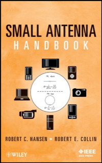
On the other hand, some highly reputable and distinguished experts have said that fractals offer no real benefits. For example, in their “Small Antenna Handbook” (IEEE Press/Wiley), experts Robert C. Hansen and Robert E. Collin reviewed many papers on fractal antennas (Figure 5). One review of the book noted that they concluded that these antennas offer no advantage over fat dipoles, loaded dipoles, or simple loops and that “nonfractals are always better.”
Q: Is that the only doubting review?
A: That’s not the only negative perspective on fractal antennas. For example, there’s the Antenna-Theory.com site run by Peter Joseph Bevelacqua, a practicing antenna engineer with a Ph.D. in antennas (see his thesis “Antenna Arrays: Performance Limits and Geometry Optimization”) who has worked for many years in defense, university, and consumer electronics as an antenna engineer. On the site, he goes step-by-step through the construction of a bowtie/triangle (a Sierpinski gasket) fractal antenna and then tested it. He concludes that the fractal was slightly better in some attributes and worse in others, but there was no clear-cut advantage,
Q: What can we conclude from these contrary views on fractal antennas?
A: I am not in a position to make any sort of definitive statement, of course. I suspect the difference in the fractal antenna yes/no view depends on the relative importance of the different attributes in the target application. There is no such thing as a “better” antenna, but there are antennas that perform better in some respects than other antennas and worse in others. It’s likely really a matter of what the priorities are and what constraints bound the design.
It’s analogous to asking, given the thousands of distinct op-amp models available, “Is XYZ a better op-amp than ABC?” The answer is a function of the answer to the questions “better in what way?” and “better by how much?”
Related WTWH content
Demonstrating antenna diversity, Part 1: The challenges
Demonstrating antenna diversity, Part 2: The PIFA
Demonstrating antenna diversity, Part 3: The Yagi antenna
What materials can be used to make miniature antennas?
The basics of dielectric resonator antennas
How distributed antenna systems bring cellular indoors
Getting one wire to do more, Part 4 – headphone wire as antenna
Getting one wire to do more, Part 3 – Powering the antenna LNA
Software tool helps designers place antennas in design
5 tips for designing with embedded antennas
Metamaterials, mmWave antennas, 3D radar and holographic beamforming
mmWave antennas and antenna management for 5G
The microstrip antenna, Part 1: Basics
The microstrip antenna, Part 2: Implementation
External references
Jem Engineering, “Fractal Antennas, Explained”
IEEE Insight, “Why Mobile Phones Can Do So Many Things: The Invention of The Fractal Antenna”
Antenna-Theory, “Fractal Antenna”
U.S. Patent 6,452,553, “Fractal Antennas and Fractal Resonators”
The Oracles Library, “Sacred Geometry: How Cell Phones Work Using Fractals”
Yale University, “Fractal Geometry”
Hackaday, “Fractals Among Us”
Peter Joseph Bevelacqua Ph.D. thesis, “Antenna Arrays: Performance Limits and Geometry Optimization”
Wikipedia, “Fractal Antenna”
Wikipedia, “Benoit Mandelbrot”
Wikipedia, “Sierpiński carpet”