The microstrip antenna is a convenient, planar, easy-to-fabricate antenna with some attractive attributes and features, as well as some distinct limitations.
Part 1 of this FAQ was a brief review of antennas and introduced to microstrip antenna design. This part continues that exploration along with related issues.
Q: What’s the difference, if any, between a microstrip antenna and a patch antenna?
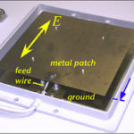
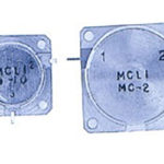
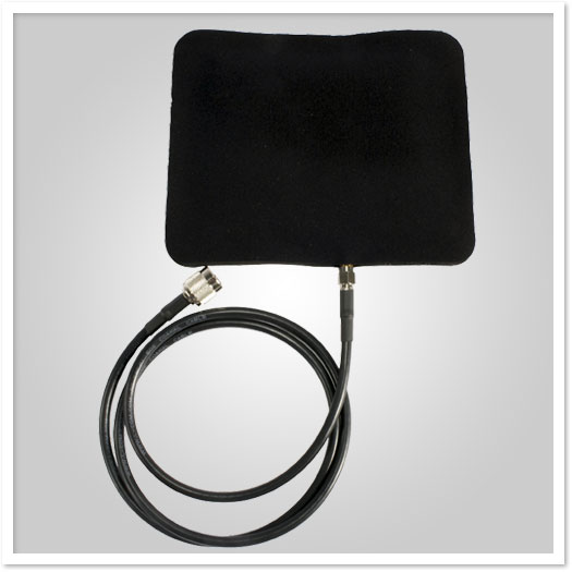
A: There really is none. In a strict sense, “microstrip” refers to this antenna as a concept, while “patch” refers to its actual realization as a discrete component. You can buy patch antennas as standard components from many sources (Figure 1). In practice, the terms are used interchangeably.
Q: There is also the term “stripline” – what’s that?
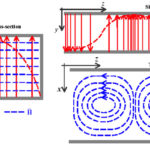
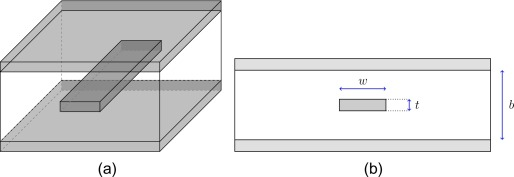
A: A stripline is a way to create an RF transmission on and in a PC board, rather than use discrete wiring or coaxial cables, (Figure 2). It is a center conductor surrounded by dielectric material with top and bottom metal ground planes. The stripline is a cost-, space-, and RF-efficient way to create a transmission line having almost any resistive or reactive impedance. It so can be used for both power conveyance and impedance matching between source and load. The stripline is often used between a source and antenna, such as a microstrip antenna.
Q: What are the basic equations of the microstrip antenna?
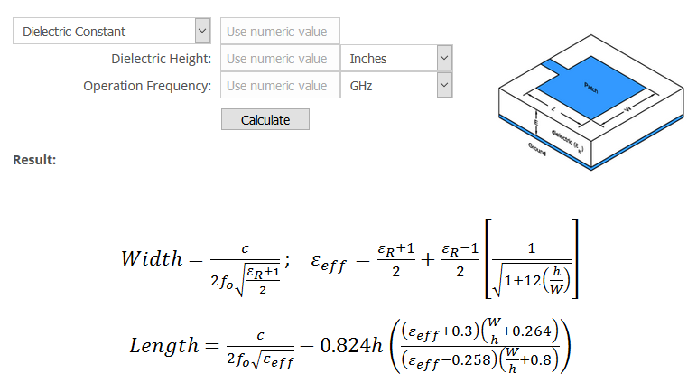
A: Due to its simple design, only a few equations are needed (Figure 3 (until real-world aspects are also included), and while they seem complex at first, they can be easily calculated. Some venders offer a simple online calculator, where you enter the desired operating point, and it returns the dimensions.
Q: What is the radiation pattern of the microstrip antenna?
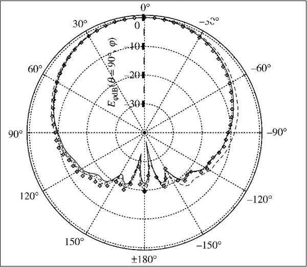
A: The broadside pattern, normal to the antenna plane, is shown in Figure 4. The radiation pattern of microstrip or patch antenna is fairly broad, with low radiation power and narrow frequency bandwidth.
Q: What affects the real-world performance of microstrip antenna?
A: As with most RF components– especially at the multi-GHz part of the spectrum – dimensional and parameter accuracy and stability are critical. Fabrication must keep physical dimensions accurate, and these must not change appreciably with temperature, use, or installation. Further, electrical properties such as dielectric constant (typically between 2.0 to 10.0) are also critical and must be accurate, consistent, and stable. (Other factors which affect performance are discussed below.)
Q: The PIFA antenna is often mentioned in connection with microstrip antennas – what is that?
A: The PIFA – planar inverted F-antenna – is a variation of the basics microstrip/patch antenna and is often used at frequencies above 1 GHz, such as in smartphones. The antenna is resonant at a quarter-wavelength (thus reducing the required space needed on the phone), and typically has other favorable properties.
It has a DC shorting “pin” between the top-side radiating surface and the feed, but at RF frequencies this DC short is reactive and so introduces a parallel inductance to the antenna impedance (Figure 5).
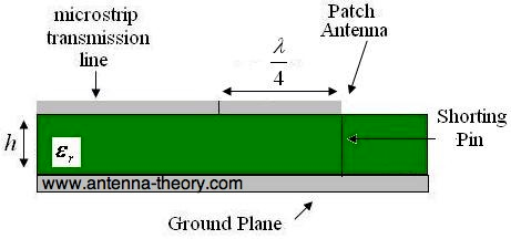
This antenna resembles an inverted letter F, which explains the PIFA name, and is popular because it has a low profile and an omnidirectional pattern.
Q: What are some of the important and distinctive characteristics of the microstrip antenna?
A: There are many. Some are positive, some are negative, and some can be either depending on the application.
One the generally positive side:
- If it is fabricated as part of the PC board, it is a no-cost option, as there is no separate discrete component or antenna.
- Performance accuracy to specifications is initially a function of the fabrication photo or laser etching, which is quite good.
- They are not limited to the simple case of rectangle geometry. Other overall shapes such as circular, spiral, star, or bowtie can be used. They can even become more complicated with slots and other deliberate irregularities, which provide some unique performance characteristics.
- The feedpoint is easily integrated with the antenna and can be part of the PC board design.
- They are relatively small for a given frequency or band, lightweight, and low physical volume.
- They are mechanically robust.
- Their design can be corrected in advance for real-world considerations such as edge-fringing or parasitics by adjusting their dimensions and shape.
- They are flat and can even be made of flexible materials and so conform to surfaces such as an aircraft fuselage.
- Multiple such antennas can be fabricated on the same surface as the antenna portion of a phased-array design.
On the less-desirable side:
- They have a fairly narrow bandwidth and increasing that bandwidth requires increasing their size.
- They are sensitive to changes in dimensional and electrical parameters of their constituent elements.
- They have low radiation efficiency due to dielectric and conductor losses.
- They have low power-handling ratings (only an issue for transmit functions).
- Their radiation pattern, shown previously, is fairly limited and difficult to adjust if it is not what the application requires.
- Although “free” if they are implemented as part of the device’s PC board rather than as separate discrete components, they require valuable PC-board real estate.
- Again, if implemented as part of the PC board, their performance characteristics are sensitive to surrounding components and will require a physical separation; alternatively, the effects of these adjacent components can be modeled to some extent and factored into the design.
Q: Is there another interesting “big-picture” aspect to these antennas?
A: Since they are low cost and usually fabricated using PC-board techniques, they can be used to create antenna designs which are difficult or impossible to build out of discrete physical elements. For example, it is possible to build a microstrip antenna which not only supports multiple bands but also provides spectrum notch filtering and signal rejection. Although the design may look complicated, as long as it can be drawn, it can be built. Advanced EM-modeling software makes it possible for radically different geometries, which have been hypothesized to be evaluated in advance with high accuracy, then fabricated and tested.
For this and other reasons, theses antennas are popular with universities and students doing advanced antenna studies, as they lend themselves to low-cost projects which involve design, modeling, fabrication, and test. Many of these designs show ingenious geometries and arrangements which yield antennas which simultaneously meet multiple challenging objectives for frequencies, bandwidths, radiation patterns, and more.
Q: Can you give an example?
A: The antenna of Figure 6 begins with a square-like patch about 78 mm on each side, which is then modified by subdividing it with fractal elements. This three-band design supports a GPS receiver at 1.575GH plus two radio bands, one at 1.78 GHz to 1.9 GHz and the other at 2.67 GHz to 2.78 GHz. This antenna would be impractical or impossible to build as a non-microstrip component. Still, as a microstrip component, the fabrication challenge is minimal, and most of the effort is in the concept, design, modeling, design, and test.
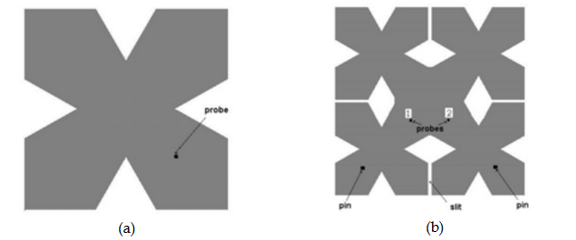
Advanced microstrip antennas are not limited to “obvious” geometries. Some have complex combinations of straight lines, curves, solid areas, curved or straight cut-out zones, and more to provide the combination of designed attributes.
Conclusion
Microstrip antennas offer a vehicle to investigate and implement antennas with unique combinations of performance characteristics and features which are favorable or at least acceptable in a given situation. They are low cost and allow for experimentation with designs that would be difficult or impossible to realize using discrete antenna fabrication. However, as with any component, they also have limitations and drawbacks which must be considered.
EE World Related Content
Take a class in SDR and antenna design
The difference between active and passive antenna systems
Hidden pitfalls of IoT antenna design
New Antenna Concept Developed for Cars
What are RF waveguides? Part 2: implementation and components
What are RF waveguides? Part 1: context and principles
5 things you need to know about 5G filters
Passive microwave components, Part 2: couplers and splitters
Passive microwave components, Part 1: isolators and circulators
How do RFID tags and reader antennas work?
References and Resources
Basics and tutorials
- Maxtena, “Microstrip Patch Antennas”
- IOP Conference Series: Materials Science and Engineering, “Design, simulation and analysis: a microstrip antenna using PU-EFB substrate”
- Pasternack, “Microstrip Patch Antenna Calculator”
- EU Radar Tutorial, “Patch Antenna or Microstrip Antenna”
- Ranga Rodrigo, Arab Academy for Science, Technology, and Maritime Transport, “Fundamental Parameters of Antennas”
- Pongsak University, Thailand, “Chapter 2 : Fundamental parameters of antennas
- Tutorials Point, “Antenna Theory – Micro Strip”
- Universal Engineering College, University of Calicut, “Radiation and Propagation: Fundamentals of Antenna”
- ResearchGate, “An Overview Of Microstrip Antenna”
- ResearchGate, “Design of rectangular microstrip patch antenna”
- ResearchGate, “Methods to Design Microstrip Antennas for Modern Applications”
- Science Direct, “Microstrip Antenna”
- Science Direct, “Stripline”
- Antenna-Theory.com, “Microstrip (Patch) Antennas”
- Antenna-Theory.com,“PIFA – The Planar Inverted-F Antenna”
Advanced microstrip antenna implementations
- Elsevier, Science Direct, “A Novel Compact Dual Frequency Microstrip Antenna”
- Elsevier, Journal of Applied Research and Technology, “Design of triple-layer double U-slot patch antenna for wireless applications”
- ResearchGate, “Methods to Design Microstrip Antennas for Modern Applications”

