The Luneburg lens is an extremely efficient reflector of radar energy based on advanced principles and fabrication techniques.
You’re undoubtedly familiar with the concept of radar, radar reflections, and the importance of minimizing reflecting in order to be less visible to a radar beam. As radar technology advanced through various improvements such as use of higher frequencies with improved resolution, more sensitive receivers, and better algorithms for processing received reflections, it became harder and harder to be less visible to radar.
Obviously, this is a concern for military operations. Improved radar could even spot and track non-metallic objects which reflected electromagnetic energy poorly, such as birds. The need for being less visible if not invisible to radar has been a goal since the earliest days of technology, which was developed during World War II. There was not much, however, that could be done to reduce the reflections back to the radar transmitter.
That all changed towards the end of the 20th century. To overcome this threat, the United States Air Force incorporated the revolutionary low-observable “stealth” technology into tactical aircraft. The first such aircraft was the F-117 Nighthawk attack aircraft introduced in 1983 (retired in 2008) which was developed by Lockheed’s famous, super-secret Skunk Works division. Other stealthy aircraft followed, including the F-22 Raptor fighter, the F-35 Lightning multirole combat aircraft, the B-2 Spirit long-range bomber, and the forthcoming B–21 Raider strategic bomber under development.
These stealthy aircraft use a combination of sophisticated techniques to be almost invisible to radar. These include unique materials and coatings, minimizing the electrical appearance of engine-exhaust ducts, and carefully designed and contoured surfaces with only smooth curves and angles that diffuse or deflect, rather than reflect, impinging radar energy.
But… what if you are in a contrary scenario and deliberately want or need to be seen by radar, whether to track a test aircraft, manage emergency situations, or even fool the enemy into thinking your small aircraft is much bigger than it really is? What are the options?
This FAQ will look at a specialized, passive radar-reflecting structure called a Luneburg lens (sometimes spelled “Luneberg”) which addresses the situation. It will also look at other uses for this fascinating device.
Q: What is the figure of merit for radar reflections?
A: It is informally called the radar signature, but the formal name is radar cross section (RCS). It is the area that intercepts the radar’s transmitted signal energy and reflects it back to the radar receiver. Radar cross-section is the ratio of backscatter power to the power density received by the target, Figure 1. It is generally denoted by the lower-case Greek letter sigma (σ) and has units of meters2.

Q: What factors affect RCS?
A: There are many. Obviously, the size of the target is a key factor. Other factors include the target’s materials and its coatings or paint, the angle of incidence at which the radar energy hits the target, and the presence of sharp edges or angles in the target. RCS has been studied extensively with many geometric-based models, analytical expressions, and, of course, tests on scale models in electronically shielded chambers as well as with actual aircraft ships, cars, and more.
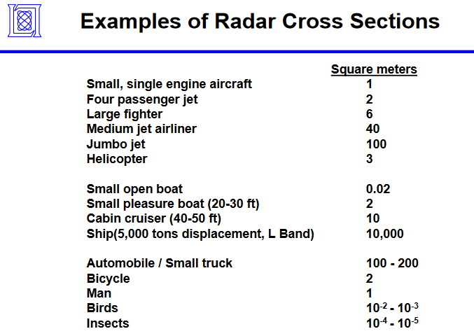
Q: What are some typical RCS numbers?
A: The table gives you some representative numbers and shows the many orders of magnitude that RCS can span, Figure 2. Note that RCS will vary by a factor of two, five, or more depending on the aspect of the incident energy: the head-on RCS of an airplane is far smaller than its broadside RCS.
Q: What is the RCS of the stealthy F-117 and the F-22?
A: While the numbers are classified, the best estimates are that the RCS for the F-117 is 0.003 meter2 while the F-22 is 0.0001 meter2. For perspective, those numbers are equivalent to the RCS of a small metal ball bearing.
Q: It seems like the objective is to minimize RCS, so why would you want to increase it?
A: You need to increase it to be seen on the radar when appropriate or necessary. For example, if you are tracking a stealth aircraft as part io a test how do you see it on radar without radically reconfiguring the aircraft itself (obviously impractical and undesirable)? After all, unlike in the movies, aircraft stealth mode is not a “cloaking mode” controlled by a switch that the pilot can flip in the cockpit — the shape is in stealth mode “on” all the time.
Alternatively, you may want to make your small aircraft or missile look much larger and misleading on the tracking radar of the enemy, thus confusing their response and perhaps causing a misallocation of defensive resources or reactions.

The need to be seen doesn’t just apply to stealthy aircraft in test modes. Commercial ships want and need to be seen on the radar for safety and maneuvering purposes.
Q: What is a solution?
A: It’s obviously impractical to mount relatively large, flat sheets of metal with their larger RCS to an aircraft as they would adversely affect the aerodynamics and handling and could loosen and be blown off. A basic sheet-metal reflector may work for a marine vessel such as a sailboat, Figure 3, but not for an aircraft.
What is needed is a relatively small, fairly streamlined passive device that reflects impinging electromagnetic energy back to the source. One such widely used device is the Luneburg lens, which will be discussed in the next section.
Related EE World Content
Device Turns Flat Surface into Spherical Antenna
Lens antennas focus multiple wireless beams
Improved estimation of automotive radar signal strength
Evolving radar technology in ADAS
How many types of radar are there?
Metamaterials, mmWave antennas, 3D radar, and holographic beamforming
Understanding decibels and decibel measurements
The why, where, and how of automatic gain control, Part 1
External References
The Aviation Geek Club, “How Luneburg lens radar reflectors are used to make stealth aircraft visible on radar screens”
3DFortify, “3D Printing for RF & Microwave Devices”
Fortify, “State-of-Technology Update On GRIN/Luneburg Dielectric Lenses/Antennas for Microwave/mmWave Applications”
Wikipedia, “Luneburg lens”
Rozendal Associates, “Luneburg Lenses”
RF Wireless World, “Advantages of Luneburg Lens | disadvantages of Luneburg Lens Antenna”
Mayurakshi, “Luneburg Lens”
Military Embedded Systems, “Radar cross section: The measure of stealth”
MIT Lincoln Laboratory, “Introduction to Radar Systems: Target Radar Cross Section”
RF Cafe, “Radar Cross Section (RCS)”
West Marine, “Selecting a Radar Reflector”
National Boating Safety School (Canada), “Boat Radar Reflector Requirements”
ITU, “Technical Parameters of Radar Target Enhancers”