Low-noise circuitry is critical to image quality of medical ultrasound, an indispensable diagnostic tool.
Efficiency versus noise
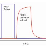
It may seem that if there is a tradeoff between power-supply noise versus potential efficiency, the need for ultralow noise in the ultrasound application should prevail. After all, a few more tens of milliwatts of dissipation should not be that much of a burden at the “big-picture” system level. Further, why not increase the energy pulsed by the transducer to increase the pulse signal strength and thus the reflected SNR?
But this tradeoff has another complication: self-heating in the handheld digital probe which contains the transducer, piezoelectric element driver, AFE, and other electronic circuitry. Some of the probe’s electrical energy is dissipated in the piezoelectric element, lens, and backing material, thus causing transducer heating. Along with wasted acoustic energy in the transducer head, this will result in heating raising the temperature of the probe.
There is a limit on the maximum allowable transducer surface temperatures. IEC standard 60601-2-37 (Rev 2007) restricts this temperature to 50°C when the transducer is transmitting into the air and 43°C when transmitting into a suitable phantom (a standard body simulator); that latter limit implies that skin (typically at 33°C) can be heated up only by 10°C at most. Thus, transducer heating is a significant design consideration in complex transducers. These temperature limits may effectively restrict the acoustic output that can be employed independent of available DC power.
Electronic noise types and their appearance
Although in-body and patient-induced signal noise is beyond the control of the ultrasound-system designer, internal circuit noise must be managed and controlled. To do so, it’s important to understand the noise types, their impact, and what can be done to reduce them. The primary areas of concern are switching-regulator noise; white noise due to signal chain, clock, and power; plus layout-related noise.
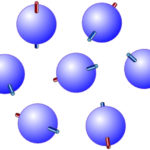
There are also various types of electronic-circuitry noise including shot (Poisson), 1/f, and white (Gaussian) noise of the components (Figures 1, 2, and 3), which are due primarily to various fundamental mechanisms associated with the basic physics of materials, solid-state devices, and thermal activity (the underlying random processes and their mathematical descriptions are complex subjects and not discussed here).
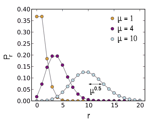
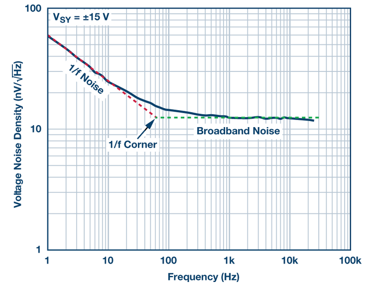

These noise sources are characterized by probabilistic formulas that characterize their random nature. To minimize their impact, designers choose low-noise analog components such as amplifiers, follow “best practices” for physical layout, and add analog filtering, ground planes, and even discrete shielding in some cases.
There is also noise which is due to the radiated or conducted noise created by the internal clocking and switching operation of DC-DC switching regulators. The function of providing the needed DC rails from higher or lower voltage DC sources (called buck or boost modes, respectively) presents an engineering “either/or” dilemma — at least until recently, as will be explained later.
Why is this a dilemma? The venerable low dropout regulator (LDO) provides buck regulation with a very low-noise output, typically on the order of a few microvolts. It is, however, also very inefficient in the 50 percent range. This not only wastes power but generates heat which must be managed, affects system reliability, and even limits the maximum power of the ultrasound system pulses.
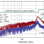
The alternative to the LDO is the switching regulator (“switcher”). This regulator is very efficient, usually at 90 percent or better, and so minimizes the thermal and heat issues of the LDO. Switchers, however, are inherently noisy, producing wideband noise spikes at their clock frequency as well as harmonics (Figure 4). These noise spikes are typically on the order of ten to twenty millivolts.

There are other issues with switching regulators. Most switching regulators use a simple resistor to set the switching frequency. The unavoidable tolerance band of the nominal value of this resistor introduces different switching frequencies and harmonics on the PC board as the frequencies of the different independent regulators mix and cross-modulate each other.
Consider that even a tight-tolerance resistor with 1% inaccuracy results in a 4-kHz harmonic frequency in a 400-kHz DC-to-DC regulator. This makes the impact of the harmonics harder to control.
One solution is to select a switching regulator IC with a synchronization feature implemented via a synchronization connection on one of its package pins. Using this feature, an external clock can distribute a signal to the multiple regulators, so they all switch at the same frequency and same phase. This will eliminate the mixing of the nominal frequencies and the creation of associated sum/difference frequency components.
Another technique is to use a switching regulator which employs random spread-spectrum clocking to spread the generated electromagnetic interference (EMI) across a wider band while lowering its peak value at any specific frequency. While this is an attractive solution for some applications which are less SNR-critical and more concerned with meeting EMI requirements, it introduces uncertainties in the resultant harmonics which will be created across a wider spectrum and thus harder to control.
For example, a switching-frequency spread of 20% for EMI consideration results in harmonic frequency between zero and 80 kHz in a 400-kHz power supply. Thus, while this approach to lowering EMI “spikes” may help meet relevant regulatory mandates, it may be counterproductive for the special SNR needs of ultrasound designs.
Until recently, there was no “middle ground” or way to make tradeoffs between the low noise and low efficiency of the LDO versus the higher noise with high efficiency of the switcher, as their differences were due to the fundamentals of their topologies. In other words, designers could not choose an LDO with, for example, 20 percent greater noise exchange for some improved efficiency. That option did not exist.
In the end, most designers chose to go with the higher efficiency of the switching regulator and use small, lower-current LDOs in a few selected areas. To make this work, they must make some difficult decisions in the selection of the switching frequency (which can range from several hundred kilohertz to a few megahertz) and make judicious use of various filters including capacitors and ferrite beads, extra ground planes, and shielding.
In recent years, however, a new class of solution has been developed offering a superior option: low noise switching regulators. These use innovative internal designs, integrated passive components, advanced packaging techniques, and other approaches to produce regulated outputs that are almost as low noise as LDOs, in the low-microvolt range (Figure 5). These ultra-low noise switching regulators are available from vendors such as Texas Instruments, Analog Devices (trademarked as silent switchers), and others, and thus minimize the “either/or” conundrum.

Conclusion
Ultrasound imaging is a widely used, invaluable, noninvasive, and risk-free medical-imaging tool. Although the basic principle is conceptually simple, designing an effective imaging system requires a significant amount of complex circuitry along with multiple DC regulators to power its various subcircuits. These regulators and associated power must be efficient but also be very low noise due to the extreme SNR and dynamic range mandates on the reflected acoustic signal energy. LDOs and especially ultra-low-noise switching regulators meet these requirements without compromise in space, EMI, or other performance attributes.
EE World References
Signal generator board produces complex waveforms for ultrasound transducers, medical apps
High-voltage analog switch ICs handle medical ultrasound imaging applications
The Doppler effect: From highly ridiculed to absolutely indispensable, Part 1
External references
National Library of Medicine/IEEE, “Despeckling of Medical Ultrasound Images”
Elsevier/Science Direct, “Performance Enhancement and Analysis of Filters in Ultrasound Image Denoising”
Radiologic Clinics of North America, “The Essentials of Extracranial Carotid Ultrasonographic Imaging”
Maxim/Analog Devices, “Overview of Ultrasound Imaging Systems and the Electrical Components Required for Main Subfunctions”
Analog Devices, “Ultrasound Analog Electronics Primer”
ST Microelectronics, “STMicroelectronics introduces highly integrated 32-channel ultrasound transmitter optimized for handheld scanners”
ST Microelectronics, “Products and solutions for Medical Ultrasound”