Basic passive microwave components have a vital role in RF/microwave system design. Despite the apparent simplicity of their functions, their performance is based on electromagnetic theory and Maxwell’s equations for insight into their operating principles and performance.
Design for the demands of microwave signals is a very different situation than working at lower frequencies. Although there is no single formal definition of which frequencies constitute microwaves, one widely used definition is that it concerns wavelengths ranging from about one meter to one millimeter with corresponding frequencies between 300 MHz and 300 GHz respectively. Others feel that the real world of microwaves begins at around 1 GHz.
Regardless of the definition you use, the microwave world is defined and characterized by parameters which differ significantly from those of lower frequencies. Instead of voltage, current, and resistance linked by Ohm’s Law, it’s a world of RF power and energy and defined by Maxwell’s equations and the interaction of electric fields with magnetic fields in many cases. The objective of a typical microwave design is to guide, route, amplify and attenuate power, and translate frequencies (if needed) to meet project objectives.
The world of microwaves is bounded on one side by lower frequencies with which more engineers are familiar, and on the other side by the very different world of terahertz waves and even optics. While all parts of the electromagnetic spectrum are ultimately governed by the same basic equations, the reality is that the appearance and disposition of those equations differ widely between regions.
Despite the well-deserved attention that active devices such as PAs, LNAs, and ICs receive, passive devices are a large part of the microwave story. This article will look at some passive devices which are used in the microwave world and are as commonplace as resistors, inductors, and capacitors are at lower, non-microwave frequencies. Unlike R, L, and C devices and their relatively simple equations which define their basic voltage and current relationships, these microwave devices can only be formally analyzed using advanced mathematics and electromagnetic (EM) theory.
These operating principles, design, and construction are perhaps “alien” to engineers whose design experience is primarily at lower frequencies. But these “strange” devices must be understood in order to develop systems for the ever-growing needs of microwave design. Part 1 of this discussion looks at isolators and circulators, which are closely related devices. Part 2 will look at couplers and splitters.
Q: What is an RF isolator?
A: An RF isolator is a two-port device which prevents RF energy from coming back to its source. It is analogous to a diode which only allows electrical current to flow in one direction, or a check valve in a fluid-flow system. Note that the RF isolator has absolutely no relationship to galvanic (ohmic) isolation used in non-RF signal and power-supply designs, and it is not galvanically isolated.
Q: Where and why is an isolator needed?
A: It is primarily used to protect other RF components from excessive signal reflection. For example, isolators are used in test applications to provide electrical separation between a device under test (DUT) and a sensitive signal source. This is done in the event that some of the energy at the DUT reflects back to the source (Figure 1).

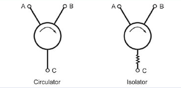
Q: What is a circulator?
A: As the larger “sibling” of the isolator, the circulator is a three-port device used to control the direction of signal flow (RF energy) in a circuit. Note that an isolator is a circulator with its third port terminated (Figure 2).
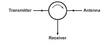
Q: Where is a circulator used?
A: The most common application is where a transmitter and receiver share an antenna, and the higher-power transit signal must not reach the sensitive receiver input as it would overload and possibly damage it (Figure 3). (The general term for this function is a duplexer.) Ideally, the transmit signal energy output would go only to the antenna port and not be “seen” by the receiver. (Note that there are other ways to implement the duplexer function, including using a more-expensive cavity duplexer.)
Q: How are isolators and circulators fabricated?
A: Though it may seem strange, they use ferromagnetic materials. While it is necessary to use scattering parameters (S-parameters) to characterize the isolator or circulator fully, their underlying principle is that their material and construction is non-reciprocal, with a non-symmetric scattering matrix. The non-reciprocal material used is a ferrite substance is biased by a static magnetic field. The positioning of the ferrite is such that the microwave signal presents it with a rotating magnetic field, with the rotation axis aligned with the direction of the static bias field.
Depending on the rotation with respect to this biasing field, the behavior of the ferrite changes and is different for microwave signals traveling in opposite directions. Therefore, energy leaving one port exits at the next port, but energy reflecting from that second port cannot propagate back to the first port.
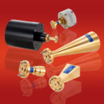
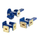
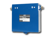
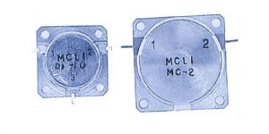
Q: How are these isolators and circulators packaged?
A: They are generally offered as discrete devices in shielded metal cans, with appropriate connectors for the input and output ports (Figure 4). They are also available in waveguide, coaxial, and even “drop-in” microstrip varieties (Figure 5) which are often used in transmit/receive modules to “duplex” an antenna between the transmitter power amplifier (PA) and receiver low noise amplifier (LNA).
Q: What are the key performance parameters and their typical values?
A: These are the ones most commonly associated with RF deices and functions (as passive devices, they provide no gain, of course):
- Isolation: typically 10 dB to 25 dB, depending on the VSWR match between isolator/circulator and load.
- Insertion loss: anytime there is a device between a source and a load, there will be some loss. Insertion loss for these devices is typically under 1 dB.
- Power handling: unavoidable losses in the ferrites lead to heat which must be dissipated as excess temperature which can reduce or damage the effectiveness of the ferrite material. Power-handling is a function of size, and standard devices are available which can handle tens and hundreds of watts.
- Bandwidth/frequency range: this is a function of the ferrite material, and the unique, proprietary “mixes” that various vendors use. Standard isolators and circulators are available into the tens of GHz.
Q: What are some of the limitations of these devices?
A: There are several. First, their size and bulk make then incompatible with today’s miniature products which must, therefore, use alternative approaches which are only viable at lower-power levels. MEMS-based approaches are another technology which is also being investigated. Second, it is difficult to achieve acceptable performance beyond tens and hundreds of GHz, although new technologies are being developed to do this (see Reference 7).
This FAQ has looked at two basic and essential passive RF devices. The next part will look at two others: couplers and splitters.
EE World Online References
Coax power splitters/dividers, directional couplers, attenuators cover dc to 110 GHz
Single-input, dual-output power splitter designed for mid- and high-end smartphones, tablets
Coaxial components cover frequencies from dc to 110 GHz
Cross guide couplers with 4, 3 or 2 waveguide ports work across C to K bands
Cross-guide waveguide couplers carry up to 4-port interface
Waveguide directional couplers work up to 33 GHz
Surface-Mount Bi-Directional coupler provides 200W power handling from 225 to 450 MHz
References
- Wikipedia, “Isolator (microwave)”
- Wikipedia, “Circulator”
- Nova Microwave, “Understanding Circulators & Isolators”
- MECA Electronics, “Isolator/Circulator Basics”
- Microwaves & RF, “A Primer on Circulators and Isolators”
- Microwaves101, “Circulators”
- Microwave Journal, “Recent Advancements in mmWave Isolator Technology”
- Microwaves101, “Directional Couplers”
- TutorialsPoint, “Microwave Engineering – Directional Couplers”
- SlideShare/LinkedIn, “Microwave Couplers”
- Marki Microwave, “Microwave Power Dividers and Couplers Tutorial”
- Wikipedia, “Power dividers and directional couplers”