• Skip to primary navigation
  • Skip to main content
  • Skip to primary sidebar
  • Skip to footer

Analog IC Tips

Analog IC Design, Products, Tools Layout

  • Products
    • Amplifiers
    • Clocks & Timing
    • Data Converters
    • EMI/RFI
    • Interface & Isolation
    • MEMS & Sensors
  • Applications
    • Audio
    • Automotive/Transportation
    • Industrial
    • IoT
    • Medical
    • Telecommunications
    • Wireless
  • Learn
    • eBooks / Tech Tips
    • FAQs
    • EE Learning Center
    • EE Training Days
    • Tech Toolboxes
    • Webinars & Digital Events
  • Resources
    • Design Guide Library
    • Digital Issues
    • Engineering Diversity & Inclusion
    • LEAP Awards
    • Podcasts
    • White Papers
    • DesignFast
  • Video
    • EE Videos
    • Teardown Videos
  • EE Forums
    • EDABoard.com
    • Electro-Tech-Online.com
  • Engineering Training Days
  • Advertise
  • Subscribe

What is common-impedance coupling?

December 19, 2016 By Janet Heath

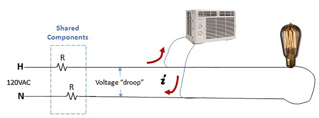
Common-impedance coupling occurs when two or more circuits share a common ground and is the result of a shared impedance in a shared ground path. The best way to explain it is by way of a common example, such as when the lights dim when an air conditioner is turned on; they probably share the same wire for the return current. The shared wire represents an impedance that is common to both the light fixture and the AC unit. The path of current through the resistors is the same path of current for the light bulb.

Anytime the AC motor’s current path and the light fixture’s current path overlap in shared components, the current multiplied by the impedance of the components (resistor) determines the value of the voltage dip that the downstream device (light bulb) experiences as a result of the upstream current draw (motor). The motor turns on, and the light dims momentarily. “Voltage droop” can be measured to show the lower than expected voltage potential for the light bulb, which causes the dimming.

Figure 1: The light bulb will dim when the AC unit induces current flow through shared components, which lowers the voltage drop for the light bulb to a “voltage droop” level, causing it to dim momentarily as high in-rush current flows when the AC unit is first turned on. A bulb that is constantly dim while the AC unit is energized means that the AC unit is constantly drawing a high enough current through the shared wire or component. Wires have resistance, and V=iR (Source: Janet Heath, with clip art courtesy of Lowes.com.)

In a PCB ground plane, the effect of current flowing through the ground plane is experienced differently at different points in the ground plane. For a sensitive analog signal, the PCB ground plane is “infected” with varying currents and voltage noise, and there is no ideal ground plane in reality. It is necessary to know the actual path that a current signal takes in its return path through the ground plane if EMC noise is to be avoided. For digital designs, a .1mV noise source doesn’t register. But for very sensitive analog signals, a millivolt can be a noise problem. From the analog perspective, if there’s a lot of current flowing through one portion of a PCB ground plane, it’s prudent to move away from that area of the board to avoid noise. In other words, circuits with large differential power levels on a common PCB should avoid the same ground return path.

Figure 2: Printed Circuit Board ground plane experiment. Testing the voltage drop at each set of points (black dots) down the ground plane demonstrates less current interference will occur the further away you get from a “busy,” high current flow trace. (Source: Janet Heath.)

The problem compounds if there is a high-frequency signal involved, as in general, ground inductance becomes dominant above 1MHz in the ground plane of the PCB example in Figure 2. For high-frequency signals (generally above 100kHz), multi-point ground systems should be used to minimize the ground impedance and inductance. For current signals with frequencies below 1MHz (for audio interference), current in the reference plane will flow through the least resistive path. Above 1MHz (for radio signal interference), it tends to flow the least inductive path.

Thus, current signals at lower frequencies are dominated by common-impedance coupling. Current signals at higher frequencies are dominated by common-inductive coupling. However, the size of the structure also plays a part in both cases. The “boundary frequency” where the signal becomes more influenced by shared inductance differs according to physical size. For example, with small integrated circuits, the “boundary frequency” where low frequency impedance-dominated current flow gives way to high frequency inductive-dominated current flow is around 20GHz. For larger structures like transmission towers, the boundary between low frequency resistive-dominated current flow and high frequency inductive-dominated current flow happens below 60Hz.


Filed Under: FAQ, Featured, Industry Experts, Products

Primary Sidebar

Featured Contributions

Design a circuit for ultra-low power sensor applications

Active baluns bridge the microwave and digital worlds

Managing design complexity and global collaboration with IP-centric design

PCB design best practices for ECAD/MCAD collaboration

Open RAN networks pass the time

More Featured Contributions

EE TECH TOOLBOX

“ee
Tech Toolbox: Internet of Things
Explore practical strategies for minimizing attack surfaces, managing memory efficiently, and securing firmware. Download now to ensure your IoT implementations remain secure, efficient, and future-ready.

EE LEARNING CENTER

EE Learning Center
“analog
EXPAND YOUR KNOWLEDGE AND STAY CONNECTED
Get the latest info on technologies, tools and strategies for EE professionals.

EE ENGINEERING TRAINING DAYS

engineering

RSS Current EDABoard.com discussions

  • Spice model for diode for rectifier simulation
  • Can I Flip Primary Connections on Mini-Circuits TCN1-10+ to Invert Output Polarity?
  • i need an embedded c program that will read a 12 bit memory address from the io pins and output the data to pins from the memory in a 8051 mcontroller
  • Power on delay circuit
  • Help with HFSS: Mesh error, found 6 bodies without triangles

RSS Current Electro-Tech-Online.com Discussions

  • 12v battery, 18v magic
  • Back to the old BASIC days
  • Need help in repairing a dead motherboard
  • LED circuit for 1/6 scale diorama
  • how to work on pcbs that are thick
“bills

Design Fast

Component Selection Made Simple.

Try it Today
design fast globle

Footer

Analog IC Tips

EE WORLD ONLINE NETWORK

  • 5G Technology World
  • EE World Online
  • Engineers Garage
  • Battery Power Tips
  • Connector Tips
  • DesignFast
  • EDA Board Forums
  • Electro Tech Online Forums
  • EV Engineering
  • Microcontroller Tips
  • Power Electronic Tips
  • Sensor Tips
  • Test and Measurement Tips

ANALOG IC TIPS

  • Subscribe to our newsletter
  • Advertise with us
  • Contact us
  • About us

Copyright © 2025 · WTWH Media LLC and its licensors. All rights reserved.
The material on this site may not be reproduced, distributed, transmitted, cached or otherwise used, except with the prior written permission of WTWH Media.

Privacy Policy