• Skip to primary navigation
  • Skip to main content
  • Skip to primary sidebar
  • Skip to footer

Analog IC Tips

Analog IC Design, Products, Tools Layout

  • Products
    • Amplifiers
    • Clocks & Timing
    • Data Converters
    • Interface & Isolation
    • MEMS & Sensors
  • Applications
  • Video
    • TI Video Channel
  • EE Forums
    • EDABoard.com
    • Electro-Tech-Online.com
  • EE Resources
    • DesignFast
    • eBooks / Tech Tips
    • FAQs
    • LEAP Awards
    • Podcasts
    • Webinars
    • White Papers
  • EE Learning Center
    • Design Guides
      • WiFi & the IOT Design Guide
      • Microcontrollers Design Guide
      • State of the Art Inductors Design Guide

Janet Heath

Sigma Delta ADC vs. SAR vs. Pipeline: How to Choose

May 24, 2021 By Janet Heath

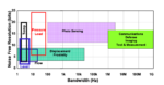
Assuming that you are familiar with the fundamental specifications of an ADC and what they mean, the next step is to know your entire signal chain well and then work to fit the ADC to the requirements. After carefully determining signal chain requirements, then select your ADC with the understanding that if the ADC is […]

Filed Under: Analog ICs, Data Converters, FAQ, Featured, Products Tagged With: basics, FAQ

Reducing ringing or reflections by controlling impedance lines

May 18, 2021 By Janet Heath

controlling impedance lines

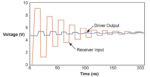
What is a controlled impedance line? For one thing, the term has to do with Printed Circuit Board (PCB) traces and layouts, which get more complex with higher frequency signals. Generally, you need not worry much about controlling impedance in traces unless you are working with signals at or above 50 MHz. However, most of […]

Filed Under: FAQ, Featured, PCB design Tagged With: basics, diodesinc, FAQ, pericomsemiconductor

Electrical noise can come from anywhere

January 3, 2021 By Janet Heath

op amp variations

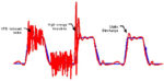
Any unwanted signal that’s combined with the desired signal is called noise. In any circuit, noise can come from anywhere; from external systems as well as from  within a circuit itself. External sources include a number of sources such as power lines, RF transmitters, nearby conductors, ignition systems, or motors that turn on and off […]

Filed Under: Analog ICs, FAQ, Featured, Industry Experts Tagged With: basics, FAQ, fluke

Amplifiers: What do rail-to-rail and single supply mean?

October 10, 2017 By Janet Heath

rail-to-rail

With respect to analog signals, a “rail” is a boundary that a signal has to work within. For a long time, operational amplifiers have required opposite but equal voltage supplies. If you see a dual-supply or dual-voltage op amp, it means that two supply voltages power the amplifier; the absolute supply voltage levels are the […]

Filed Under: Analog ICs, FAQ, Featured Tagged With: basics, FAQ

IBIS model: How can it help with signal analysis?

October 4, 2017 By Janet Heath

An Input Output Buffer Information Specification (IBIS) model is a standard in the semiconductor industry for modeling semiconductor devices from a behavioral perspective, for both analog and digital perspectives. IBIS modeling enables engineers to describe detailed signal behavior in a circuit design without revealing proprietary information about the circuits (or the processes used to make […]

Filed Under: Analog ICs, FAQ, Featured, Industry Experts, Simulation Tagged With: basics, cypresssemiconductor, FAQ, texasinstruments

Analog switch vs. digital switch ICs

August 8, 2017 By Janet Heath

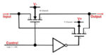
Analog switch integrated chips (ICs), when turned on, will conduct both analog and digital signals from the input pin to the output pin. Digital switches can only accept digital signals and duplicate the logic level on the input pin at the output pin. When the digital switch is turned off, it returns to a default […]

Filed Under: Analog ICs, FAQ, Featured Tagged With: analogdevicesinc, basics, FAQ, integrateddevicetechnology, intersilcorporation, maximintegrated, microchiptechnology, nxp, onsemiconductor, rohmsemiconductor, stmicroelectronicsinc, texasinstruments, vishay

Nyquist rate basics and sufficient sampling for ADCs

July 24, 2017 By Janet Heath

Converting a real-world (analog) signal into a digital signal means that you have to bring the signal into an Analog-to-Digital converter (ADC). From there, the ADC turns the continuous analog signal into a discrete, digital signal by sampling, or taking regular snapshots of, the curves of the analog signal. After sampling is complete, any information […]

Filed Under: Data Converters, FAQ, Featured, Products Tagged With: basics, FAQ

Selecting an op amp

July 18, 2017 By Janet Heath

You could start with a similar op amp from a similar, known-good circuit or reference design and extrapolate from there. However, not everything labeled a reference design has actually been built and tested. But there’s another way to get organized and feel in control of the selection process. A methodical approach is outlined below that […]

Filed Under: Amplifiers, FAQ, Featured, Products Tagged With: basics, FAQ, mouserelectronics

Compensating for DAC Offset and Gain Error

July 13, 2017 By Janet Heath

Digital-to-analog converters (DACs) are subject to gain and offset error. Errors can be compensated for with hardware by using external components or by trimming the DACs after they have been manufactured. Trimming is necessary because the error is caused by mismatched resistors; trimming attempts to change resistor values in the DAC. However, some DACs can […]

Filed Under: Analog ICs, Data Converters, FAQ, Featured, Products Tagged With: basics, FAQ

What is a multiplying DAC?

June 20, 2017 By Janet Heath

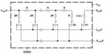
Multiplying digital-to-analog converters (MDACs) produce a (current) output signal that’s a product of the given reference voltage and the code (i.e., a string of 0s and 1s) flowing through it. All data converters require a voltage reference (VREF) and a typical, standard DAC needs a very stable fixed reference voltage in order to operate properly. […]

Filed Under: Analog ICs, Data Converters, FAQ, Featured, Products Tagged With: analogdevicesinc, basics, FAQ, texasinstruments

  • Go to page 1
  • Go to page 2
  • Go to page 3
  • Go to page 4
  • Go to Next Page »

Primary Sidebar

Subscribe to weekly industry news, new product innovations and more.

Subscribe today

EE Training Center Classrooms

EE Classrooms

A frequency you can count on There are few constants in life, but what few there are might include death, taxes, and a U.S. grid frequency that doesn’t vary by more than ±0.5 Hz. However, the certainty of the grid frequency is coming into question, thanks to the rising percentage of renewable energy sources that…

More from the archive

RSS Current EDABoard.com discussions

  • How do you find the angle made by two isosceles triangles in a kite?
  • Thermal pad construction on pcb
  • FPGA LVDS with separate clock
  • Help understanding 915MHz transciever pcb layout
  • Ansys Electronic Desktop (HFSS) file opening failed????

RSS Current Electro-Tech-Online.com Discussions

  • Flickering (candle) LED to trigger 555
  • Identify a circuit.
  • Microcontrollable adjustable and switchable constant current source for driving LED's
  • Useful Handbook for Making Low Level Measurements
  • CRYPTOOOOO, but wait i am no terrorist

Design Fast

Component Selection Made Simple.

Try it Today
design fast globle

Footer

Analog IC Tips

EE WORLD ONLINE NETWORK

  • EE World Online
  • EDA Board Forums
  • Electro Tech Online Forums
  • DesignFast
  • Connector Tips
  • Microcontroller Tips
  • Power Electronic Tips
  • Sensor Tips
  • Test and Measurement Tips
  • Wire and Cable Tips
  • 5G Technology World

ANALOG IC TIPS

  • Subscribe to our newsletter
  • Advertise with us
  • Contact us
  • About us
Follow us on Twitter Add us on Facebook Follow us on YouTube Follow us on Instagram

Copyright © 2022 · WTWH Media LLC and its licensors. All rights reserved.
The material on this site may not be reproduced, distributed, transmitted, cached or otherwise used, except with the prior written permission of WTWH Media.

Privacy Policy