
Filters are an important part of analog design. Even circuits that you don’t think of as filters are actually filters. For example, a simple amplifier will have a bandwidth and so above its upper 3dB point it is a low pass filter. Whole books have been written on filters and filter design, both analog and digital, so a short blog can only scratch the surface. Digital filters are an interesting subject but my interest is more with analog filters. Even a digital system needs a filter before the analog to digital converter (ADC) to prevent aliasing, unless one is built into the ADC.
Filters can be active or passive, high pass, low pass, all pass or notch. “All pass” sounds like a mistake but is actually a useful circuit for providing a delay which is not frequency dependent (up to a point).
The simplest low pass filter is probably a resistor and capacitor:
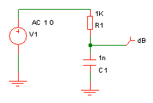
with the response below.
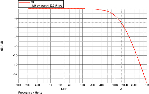
The 3dB point is simply 1/(2p RC) so 159kHz with the values shown. Filter rolloff well above the 3dB point is 6dB per octave (i.e. each doubling of frequency) or 20dB per decade (i.e. 10 times the frequency).
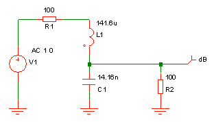
Another simple filter is an LC one.
The response is shown below, superimposed over the previous results for comparison.
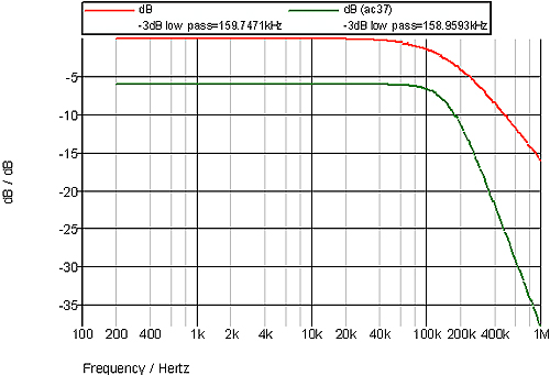
The 3dB point is the same but the rolloff is twice as steep, 12dB per octave. Note that it needs source and terminating resistors. These resistors do not have to be equal but are a critical part of the filter design. This type of filter is usually used for RF circuits where the resistors would normally be 50W. Also, note that it has a 6dB loss due to the resistors. Even so, such passive filters can be useful as anti-alias filters for an ADC provided you can live with the loss of signal. For example, below is a passive 0.5dB ripple Chebyshev filter with a 90kHz cut off which was used as an anti-alias filter for an ADC.
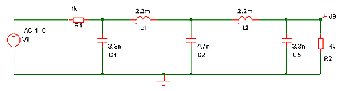
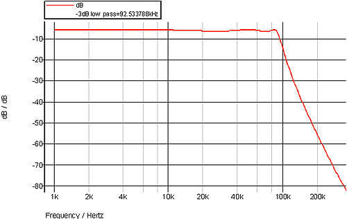
The response is shown below and the 0.5dB of passband ripple can be seen.
Care must be taken to ensure that the characteristics of “real” components still result in an acceptable performance. This is particularly true of inductors where you will have a self resonant frequency and series resistance to take into account as well as poor tolerance compared to resistors. The inductor resistance can be partially compensated for by altering the source and/or terminating resistors. All components will have tolerances and inductors are usually worse than capacitors and resistors, so they must be chosen with care.
If you are unfamiliar with terms like Chebyshev, Butterworth and Bessel then a quick internet search should help. They each have pros and cons. A Bessel filter has a constant group delay with frequency in the passband, so is useful where the shape of a signal is to be preserved. The Butterworth is a good, straightforward design – often a good compromise. The Chebyshev is more complicated as you also need to specify the passband ripple in the design – something which is not required with Bessel and Butterworth filters – but it does give the steepest cutoff for a given number of poles.
Below is a comparison of four 4 pole filters each with 1kHz cut-off. They are Bessel, Butterworth and Chebyshev with 0.1dB and 0.5dB ripple.
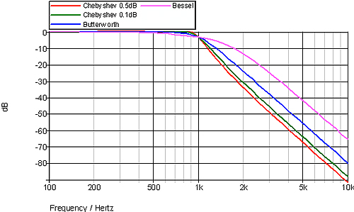
You can see how the Bessel filter is the “softest” and the 0.5dB Chebyshev is the sharpest. Note that they are all 4 pole filters and therefore all roll off at 24dB per octave well away from the 3dB point. What is different is how quickly the response drops around and above the 3dB point – the “sharpness”. Another difference between the filter designs is how they respond to a step input or pulse:
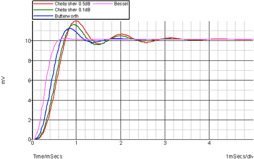
As you can see, you don’t get anything for nothing. The sharper cutoff of the Chebyshev filters comes with a lot of overshoot compared to the Bessel – something that could be critical depending on the nature of your signal. So, choosing the correct filter response – number of poles, response type and ripple is important.
While I have only covered passive filters, exactly the same filter types and characteristics exist for active filters. An active filter usually uses resistors and capacitors, avoiding the problematical and sometimes impractical inductors. Instead, they provide the same effect as using inductors without actually needing to use them.