Peer-to-peer, engineer-to-engineer questions and answers from the EDABoard.com engineering community around analog ICs and analog design. Click the “Read more” link and follow the entire conversation and maybe add your two cents by logging in to EDAboard.com.
OR wired with diodes to control the gate in a PMOSFET – I have two outputs from an open collector IC connected to diodes to achieve an OR wired. The circuit is used to control the turn ON and turn OFF of a PMOSFET. Shall I use a pull-up resistor in the source input of the PMOSFET? Does the design need a pull-down in the PMOSFET gate? The MOSFET is always turn ON, even when the gate is 5V, how is it possible? Read more
Variable current sense – I’m in doubt if this would work as a variable current sense circuit, especially the R1/R2 voltage divider. I would like to make a R2 variable. Would that work? LTSpice says it will, but I intend to place this on a SMPS so I’m not sure, noise and real-life working conditions you know. Read more
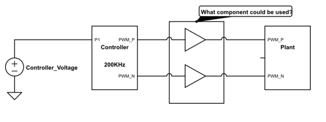
Stable PWM during voltage loss – I have a system as below, controller runs at 200 kHz. I have a requirement of interruption at the controller voltage for 50 μs. Still, during that, I need to have the PWM running. I have one option to have hold circuit for the controller to stabilize the voltage, to avoid the big Cap to be used. I thought of using PLL in between. But the PLLs duplicates the frequency. What could be considered? Read more
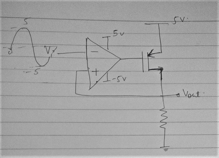
Output of the circuit – Kindly explain how the large-signal input will affect this circuit’s output. What should be done if I want the output of the circuit to be oscillatory? Read more
Oscillator jitter transient simulation in spectre – I am currently designing a ring oscillator of 100-200 MHz frequency, and have to measure the absolute jitter using transient simulation. The schematic consists of a 5 stage ring oscillator and an ideal voltage source of 1 V to power the oscillator. A jitter was measured using abs_jitter function, which is a built-in function in the calculator of ADE X environment. Since the function compares and measures a switching timing difference between the oscillator and an ideal clock, if any noise source is not inserted in the circuit, resulting jitter value should be same, if simulated well. However, whenever I simulate the circuit, changing some settings like simulation time or an additional circuit, resulting jitter varies drastically even though the schematic is not changed. Read more
PWM during voltage loss – Refer the attached schematics, I have a system as below, the controller runs at 200 kHz. I have a requirement of interruption at the controller voltage for 50 μs, still during that I need to have the PWM running. I have one option to have hold circuit for the controller to stabilize the voltage, to avoid the big Cap to be used. I thought of using PLL in between. But the PLLs duplicates the frequency! What could be considered? Any suggestions. Read more

Circuit to pulse from 1v to 1.1v repeatedly – We need the “Output” of the following circuit to go from 1v to 1.1v as shown in the LTspice simulation. We are worried we may get too much VCE drop in the pnp….the datasheet does not tell the vce drop for our conditions, but can you agree that our Vce will be less than 10mV when ON? Read more
Fully differential opamp’ s output is not symmetrical – The transimulation of a fully differential opamp likes the following figure, the frequency of input signal is 5MHZ to obtain figure.1 and it is 100hz with figure.3. Could you explain why it is not symmetrical at the begin, I wonder why it is not similiar with figure. Read more
Low drop voltage regulator – I’m designing a battery-operated circuit where the load current will be max. 50mA.
Can I use LP2950-3.3V or MIC5236-3.3V?. Which is better. Or do you suggest another IC? Read more
Choice of capacitors to impedance matching network in RF PA – I create 150W PA for fixed frequency under 20MHz. On output is LC Impedance Matching Network and I need advice on choosing the type of capacitors.
L I create on iron powder size T130 induction around hundreds nH.C is around 900pF and my choice is use 7*150pF parallel. Voltage rating min 4xDC >=200V. In the prototype, I used silver mica, but they are expensive and I would like to avoid them. Read more
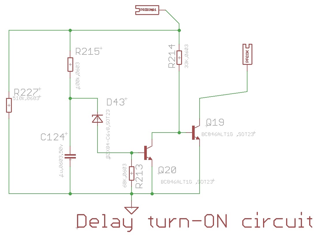
Hfe of NPN at extremely low base current – The attached is a delay circuit. When the PRIBIAS1 rail gets its 14V voltage, then Q20 holds Q19 off for some 40ms. However, the base current of Q20 can only be 50uA max. The IC in Q20 must get to some 450uA in order for it to turn Q19 off. The BC846ALT1G datasheet does not describe what happens to hfe at these extremely low currents. Do you think the circuit will be OK? Read more