Digital potentiometers – digipots – are a widely used, versatile, flexible, and feature-laden alternative to classic mechanical potentiometers.
Mechanical potentiometers are standard passive components that designers have used for decades in applications ranging from circuit trimming to volume control. However, they have their limitations: their wipers can wear out, they are susceptible to moisture ingress, and they can accidentally be moved off their set position. Further, as the world turns digital, designers need an alternative to meet requirements for more precise control and high reliability, along with the flexibility to adjust values remotely via firmware.
Digital potentiometer ICs – often called digipots – solve these issues by bridging the digital domain and the analog-resistor world. As an all-electronic, microcontroller-compatible component, digipots allow a processor and software to control, set, and vary their resistance value or voltage-divider ratio.
Digipots offer features and functions that mechanical devices cannot provide and are more rugged and reliable as they have no moving wiper. They cannot be deliberately tweaked or inadvertently adjusted, resulting in inexplicable performance changes. Applications include LED thermal stabilization, LED dimming, closed-loop gain control, audio-volume adjustment, calibration and Wheatstone-bridge trims for sensors, controlling current sources, and tuning programmable analog filters, to cite just a very few.
Begin with potentiometer basics
The potentiometer has been an essential, passive circuit component from the earliest days of electricity and electronics. It is a three-terminal device with an accessible resistor element providing a voltage-divider function via its user-settable wiper on a rotating shaft. It is used in countless analog and mixed-signal circuits to fulfill various circuit requirements (Figure 1).
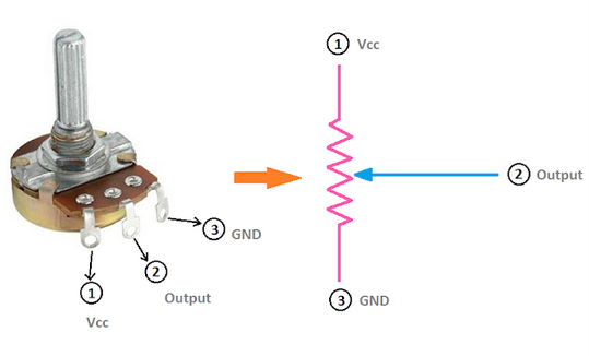
The resistance seen by the circuit between either end contact and the adjustable wiper varies from zero ohms (nominal) to the full rating of the wire or film resistance as the wiper rotates and so slides along the resistive element.
Most rotary potentiometers have a rotation range of about 270 to 300 degrees with a typical mechanical resolution and repeatability of around 0.5% and 1% of the full-scale value (between one part in 200 and 100, respectively). (There is potential for confusion here, as there are also “linear” potentiometers; these are linear in the sense they are not rotary-action devices, but instead, their control element slides along a line.)
Note that there is a slight but distinct and important difference between a potentiometer and its junior sibling, the rheostat. A potentiometer is a three-terminal device acting as a voltage divider (Figure 2, left), while the rheostat is a two-terminal adjustable resistance that controls current flow. The potentiometer is often wired to create a rheostat which can be done in one of three similar ways, by leaving an end terminal uncorrected or connected directly to the wiper (Figure 2, right).


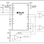
The all-electronic digital potentiometer emulates the functionality of the electromechanical potentiometer but does so using an IC without moving parts. It accepts a digital code in one of several formats and establishes a corresponding resistance value, and so is sometimes referred to as a resistive digital-to-analog converter (RDAC). The next part of this article will explore the digipot in more detail.
Related EE World Content
What is a digital potentiometer?
What’s a logarithmic resistor ladder good for?
Advanced IC integrates instrumentation amp, auto-trimming, digital pots, analog switches
Single-turn potentiometers, encoders excel at rugged industrial apps
Micro-sized slide potentiometers for consumer, audio, medical, or industrial applications
References
VivaDifferences.com, “10 Differences Between Potentiometer And Rheostat (With Comparison Chart)”
Maxim Integrated Products, “Digipot Application Ideas”
Maxim Integrated Products, Application Note 1956, “Tips to Remember When Designing with Digital Potentiometers”
Maxim Integrated Products, Tutorial 1828, “Audio Gain Control Using Digital Potentiometers”
Maxim Integrated Products, Application Note 4051,”Using an Analog Voltage to Control a Digital Potentiometer”
Components101, “How does Digital Potentiometers work, why and where should you use them?”
Analog Devices, “Choosing the Correct digiPOT for Your Application”
Microchip Technology, AN691, “Optimizing Digital Potentiometer Circuits to Reduce Absolute and Temperature Variations”
Microchip Technology, AN1316, “Using Digital Potentiometers for Programmable Amplifier Gain”
Microchip Technology, AN1080, “Understanding Digital Potentiometers Resistor Variations”
Microchip Technology, “Digital Potentiometers Design Guide”