
Sensors such as strain gauges, pressure gauges and some magnetic sensors are often bridge devices. They can be full or half bridge although the bridges are usually made of multiple devices connected together, with MEMS sensors being an exception. So, in the case of a strain gauge, a half bridge would be made with one strain gauge in tension and the other in compression so the two devices provide and equal and opposite signals.
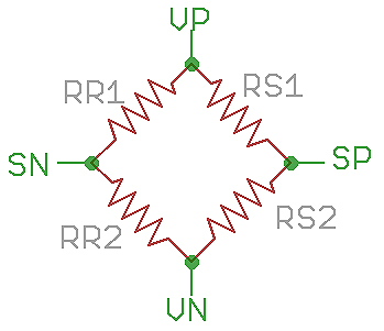
Above is an example of a bridge circuit. The resistors depend on whether you have a “full bridge”, “half bridge” or are simply a single resistive sensor. For a full bridge, all the resistors would be part of the sensor. If you have a half bridge the RS1 and RS2 would be the sensor and RR1 and RR2 would be reference resistors in your measuring system. The two resistors in a half bridge which make up the sensor would have equal and opposite resistance changes for a given actuation. For example, RS1 could increase in resistance with physical pressure and RS2 would decrease with the same pressure. So, the voltage on SP would decrease with pressure. The actual voltage you would see on SP and SN would normally be half of the excitation voltage VP – VN because at rest (i.e. no pressure) all the resistors would have an equal value. There can be limits to the maximum excitation voltage used to prevent errors due to self heating of the sensor.
This measuring system is called a Wheatstone bridge which was actually invented by Samuel Hunter Christie and not Charles Wheatstone. It was originally used for accurately measuring and unknown resistance by measuring ratios. The voltage you measure between SP and SN is really telling you about the ratio of RS1 to RS2. In this case, it is not the absolute value of the resistances that you want but the ratio of the two resistances. A bridge or half bridge sensor will usually quote a sensitivity or span such as 25mV based on 5V excitation for the All Sensors MLV-005D. As that is a 5PSI sensor, the specification is saying that with a 5V excitation (e.g. VN connected to 0V and VP connected to 5V) you will get 25mV differential voltage at 5PSI. As it is a full bridge sensor, this voltage will actually be made up of one side of the bridge moving up by 12.5mV and the other side moving down by 12.5mV.
So, the signal levels are quite small and need some signal processing. Some newer sensors have built in electronics and even an analog to digital converter and serial interface. Otherwise you need to amplify the signal to be able to use it. Being a differential signal the signals have a reasonable noise immunity, particularly for a full bridge. If you only have a half bridge, two of the resistors will be fixed values so the noise immunity will not be as good because the two signal connections will not always have identical impedances as the pressure changes.
The best way of amplifying a small differential signal which isn’t necessarily low impedance is with an instrumentation amplifier. You want a high input impedance to avoid errors due to the amplifier input impedance so something like the Texas Instruments INA118 would be an option.
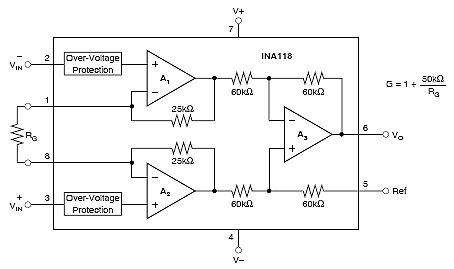
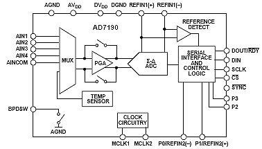
The gain is set by a signal external resistor which you would select to increase the low level signal to as much as possible of your ADC (analog to digital converter) range, assuming you actually want a digital result. Other instrumentation amplifiers exist which have preset gains and require no external resistors for setting the gain. Another option without using an instrumentation amplifier is either a high resolution Sigma-delta ADC (if your signal is large enough) or one with a built in PGA (programmable gain amplifier) as well, such as the Analog Devices AD7190.
This follows the current trend for ever more complex integrated circuits to provide complete circuit solutions where otherwise you would have had to use several integrated circuits and discrete components such as the LTC2983 from Linear technology.
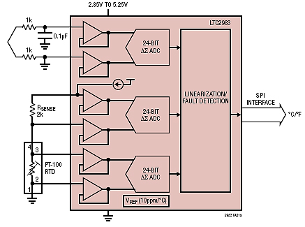
This complete multichannel digital temperature measurement system on-a-chip will work with thermocouples, thermistors, diodes and Platinum RTDs and will convert the measurement directly to temperature including scaling and linearizing.