The vacuum-tube cavity magnetron is nearly obsolete (except for the millions in consumer microwave ovens). Its development was key to highly effective WWII radar, and it also led to other RF/microwave vacuum-tube devices.
Vacuum tubes are so “yesterday,” aren’t they? They have been rendered obsolete and supplanted by solid-state devices for many reasons, except in some highly specialized applications such some radar transmitters. Similarly, the venerable cathode ray tube (CRT) which was used for decades in home TVs, oscilloscopes, user consoles, monitors, and all sorts of displays has been replaced by flat-screen units
Certainly, CRTs are gone, but there is still one vacuum tube which survives with wide use in a specific application — although it has been largely obsoleted in many others. How so? If you have a microwave oven in your kitchen, you have a vacuum tube called a magnetron in your house. Yet this humble, unassuming active device also changed the course of World War II, in the opinion of many experts and historians.
Q: What is a magnetron?
A: A magnetron is a specialized vacuum tube which does one thing: it is a power oscillator source for frequencies of several hundred MHz to several GHz. Depending on size and other factors, it can produce tens and hundreds of watts to kilowatts.
Q: Why even study this unique and somewhat obsolete device?
A: There are at least three reasons: it is still in widespread use, and millions are made every year; large ones are used for radar and broadcast operations; and it taught scientists and engineers about electronic devices which use electromagnetic principles and combine RF electric and magnetic fields, and more, resulting in important RF/microwave devices such as the traveling wave tube (TWT).
Q: What is the physics principle and basic arrangement of the magnetron?
A: Unlike an oscillator built around a resonant circuit made of discrete inductors and capacitors, a magnetron uses a unique physical structure in conjunction with a combination of electric fields, electron motion and magnetic fields in a confined metal cavity. While the magnetron is a vacuum tube, it is very much unlike a conventional vacuum tube, which uses electrons emitted from a heated cathode and which travels in a straight line to the positive charged anode, with their travel path modulated by the electric field of an intervening grid.
There is no magnetic aspect to a conventional vacuum tube. In contrast, the magnetron is a “crossed field” device which uses an electric field in conjunction with a magnetic field with their field-energy lines at right angles to each other. (The name “magnetron” is a combination of “magnetic” and “electronic”)
Q: How does the magnetron work?
A: Analysis of the magnetron can range from a qualitative explanation to highly technical analysis using advanced electromagnetic field theory and math. We’ll use the more qualitative approach.
Q: What is the physical arrangement of the magnetron?

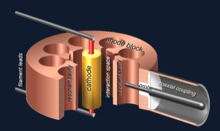
A: The basic, first magnetron – and there are many variations, of course – used a solid block of copper (for thermal dissipation) drilled with holes (called cavities) (Figure 1). The size of these cavities is critical to establishing the operating frequency of the magnetron. This physical construction and arrangement is radically different from the glass-envelope vacuum tube which had been used in an attempt to generate the short wavelengths efficiently and high frequencies needed for RF/microwave designs (1 GHz = 1000 MHz = 0.3 meters = 30 cm).
Q: How does this arrangement function when energized?
A: The cathode at the center (which is heated by a filament) emits electrons, in the same manner as the cathode of a glass vacuum tube, but that’s where their similarities end. These electrons would normally be attracted to, and travel as radial spokes, to the outer ring as an anode, which is positively charged (like the plate of a tube). However, there is a powerful static magnetic field (blue lines) aligned with the axis of the magnetron core. This field causes the electrons to instead travel in a circular flow pattern to the outer ring (red lines). The magnetic field was originally developed by electromagnets, but as more-power permanent magnets were developed years later, these were used instead.
Q: It seems as if all that has been done is to shift the static electric flow, and there is no oscillation – so how does the magnetron produce oscillation?
A: The magnetic field deflects the electrons and they “sweep” around the circle. In doing so, they “pump” at the natural resonant frequency of the cavities. The resulting current around the cavities causes them to radiate electromagnetic energy at the resonant frequency of the cavities.
Q: Is that all? How is this resonant energy made useful?
A: From a physics standpoint, work is done on the electrons, and they absorb energy from applied the power supply applied to the anode. The electrons continue to sweep and reach an energy level at which there is an excess negative charge, and that charge is pushed back around the cavity. This, in turn, imparts energy to the oscillation at the natural frequency of the cavity (pumping). The cavity is analogous to a resonant LC tank: the positive charged field is along one edge of the open side of a cavity, and the negative charged field is aligned along the other edge, so the separated row functions as a capacitor with a vacuum-gap for spacing.
Q: How is the oscillating energy extracted from the magnetron cavity and put to use in a system?
A: A coaxial coupling with a precisely sized probe is inserted sideways into one cavity to capture the energy from the block, Figure 2; it functions as a receiving antenna for electromagnetic energy.
Q: What sets the frequency of the magnetron oscillations?
A: The size and arrangement of the cavities sets the frequency, as they act as the resonant chambers. Magnetrons generally have a small adjustment screw to change the cavity size so the physical dimensions can be adjusted to resonate at the exact desired frequency despite inevitable manufacturing tolerances. Note that a magnetron is a fixed-frequency device and is not tunable, although there are some advanced and more complicated versions which have a modest tuning range.
Part 2 of this FAQ will look back at the history and role of the magnetron, and ahead to its future and possible demise.
EE World Online References
- Basics of cavity resonators
- Basics of waveguides, microwaves, and ovens
- Passive microwave components, Part 1: isolators and circulators
- Passive microwave components, Part 2: couplers and splitters
References
- Wikipedia, “Cavity Magnetron” (has links to many historical references)
- Explain That Stuff, “How Magnetrons Work”
- Georgia State University, Hyperphysics, “The Magnetron”
- Georgia State University, Hyperphysics, “Microwave Ovens”
- Microwaves101, “Magnetrons”
- Engineering and Technology History Wiki, “Cavity Magnetron”
- The Valve Museum, “CV64”
- Lamps & Tubes, “CV64 Early British S-band Cavity Magnetron”
- Radar Tutorial EU, “Magnetron”
- Ampleon N.V., “RF Solid State Cooking”
- ARMMS RF and Microwave Society, “Summary of Magnetron Development”