By Alex Grange, Siemens EDA
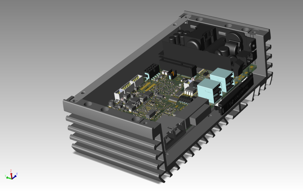
As designs grow in scope and complexity, collaboration between the electronic and mechanical domains is even more important. For example, as PCB designs face tighter requirements, problems resulting from electromechanical interference are becoming more common. Handling these problems across disciplines requires constant collaboration and synchronized data.
What isn’t working today
Most issues with collaboration can be traced back to the limitation of the format used during the collaboration.
For older designs, the Intermediate Data Format (IDF) and Data Exchange Format (DXF) provided a powerful mechanism for collaboration between electronic and mechanical domains. Yet, neither IDF nor DXF has been updated for decades. And with the evolution of the workforce, the ever-changing product complexity, and the scale of the products we design, these static formats can end up hindering the design process instead of facilitating it.
The IDF process flow restricts the frequency of electromechanical collaboration, requiring the entire data set to be transferred for each incremental collaboration exchange. Exporting collaboration data often results in electronic designers manipulating or misinterpreting information or even manually recreating the data they received. Often you need to spend a lot of time resolving issues, which is typically a very manual process, with the other domain expert looking over the shoulder of the other and a string of back-and-forth emails. Making matters more difficult, given the tight requirement of modern designs, the entire database must be represented. For example, a very common issue for electromechanical designs is the need to represent copper data in the mechanical assembly. This data must be included to identify assembly shorts and inform thermal simulation.
DXF, on the other hand, does not provide any intelligent information. Therefore, it’s up to the designer to identify and understand how each individual drawn item is associated with each item within their design. These gaps in information between electronic and mechanical design significantly increase with design complexity. Additionally, divisions increasingly function within their own silos due to the globalization of engineering groups. Thus, designers face language and time zone challenges when identifying the true design intent that another design domain is trying to convey. This lack of intelligent communication results in duplicated effort and tedious reworkings to understand the complete set of requirements set by either domain.
Because most companies’ electronic and mechanical divisions are divided, they frequently follow separate standards. Without a synchronized library structure, the product of the collaboration between ECAD and MCAD design often has components that are offset or rotated.
In some cases, the mechanical designer sends an initial baseline set of data to an ECAD designer. Right after it’s applied, the ECAD designer immediately sends a DXF file back at them. This allows the mechanical designer to overlay the placement outline and the component shape on top of the components in the mechanical assembly. Due to the complexity of the design, they have to manually comb through dozens, if not hundreds, of components to see if any component is offset. It also creates issues if the pin 1 location in the mechanical library is rotated 180 degrees from that in the electronic library.
This misalignment causes many design respins because the component looks like it was placed in the right location in the same X and Y coordinates in both the ECAD and MCAD assemblies. But, in reality, pin 1 is different, so when the component is fabricated and inserted, it will not work. Every company has its own story of how a small mismatch between the ECAD and MCAD data resulted in design respins that cost them a lot of money.
Enter IDX for electromechanical exchange
To address these costly shortcomings, the ECAD/MCAD Implementer Forum was formed in 2010 to develop the IDX standard. Its main intention was to replace IDF and DXF to provide a more incremental data exchange—rather than dumping all the data back and forth from side to side. It is essential to understand that we need to move away from these obsolete data exchange formats no longer being developed by any vendor and move toward an incremental data exchange, the IDX format.
IDX enables the creation of a more efficient and unified collaboration workflow. This workflow allows designers to accept or reject any proposed items from the other domain. To keep the data synchronized, every proposal comes with a response from the other domain. This helps to understand the board’s current status within both domains to ensure they stay in sync. This also makes it much easier to fix the problem as they are encountered, rather than doing a long design review at the end and updating the project when it’s complete.
The ECAD/MCAD Implementer Forum also wanted to provide a higher resolution of data exchange between ECAD and MCAD. Since 2010, the forum has added nine major schema updates to the IDX format, offering a wide range of features — including support for copper, solder mask, and silkscreen objects, flex, and rigid-flex designs, stack-up and primary-pin information sharing, and a lot of additional functionality that makes collaboration easier.
Establishing best practices for collaborative design
The communication between the electronic and mechanical designers should be able to occur at any time or frequency. This simplifies the exchange process, as they send only the incremental data, allowing them to collaborate more often and earlier in the design cycle.
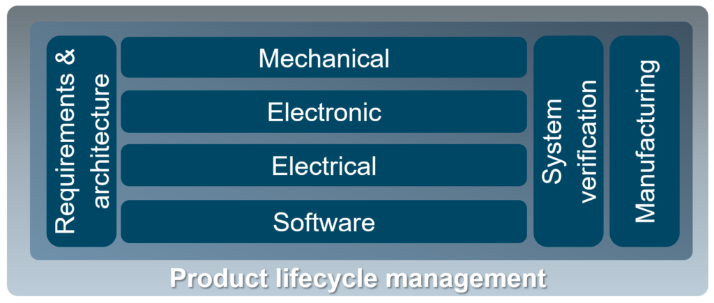
In most electromechanical projects, the mechanical designer first defines critical design constraints. This means the mechanical engineer usually defines the board outline, mounting holes, placement and routing obstructs (keep-out areas), connector placement, and other objects that may be critical for their design. This data is then exchanged with the ECAD designer to ensure the correct information is used when they start their PCB layout. This initial exchange is the baseline file, containing the entire assembly from the mechanical to the electronic domain.
With the IDX standard, design teams can go beyond sending a single static file to and from each other by allowing each domain to send incremental data, which only consists of the elements that have been added, deleted, or modified since the last incremental or baseline you have sent. Any item in the incremental data can have a comment associated with it, and the item can be accepted or rejected. Each proposal includes a response file to ensure both domains stay in sync. If a component was moved and the change was rejected, the initiator will see that it was moved back to its original location. This process continues throughout the entire design cycle until the project is finalized and sent off to be manufactured. IDX really fosters closer collaboration and enables the early identification of critical issues during the design flow.
Seeing only the items that have been added, modified, or deleted is extremely important because designers only have to find what has changed in a couple of dozen components rather than the entire database, which contains tens of thousands of objects. This ensures design consistency and synchronization and allows teams to shift left their current process and detect violations much earlier in design development.
With IDX, users can access all the relevant information in the other domain. This improves the two-way flow of information, avoids potential issues, and accelerates project development. The Siemens Xpedition and NX databases allow the mechanical assembly team to share the mechanical models directly with the ECAD designers. In the PCB layout, the designer can see in real-time, for example, the mechanical interference caused by moving a component too close to the edge of the board, thus interfering with the enclosure. One company reviewed all their PCB design respins over the last year and found that mechanical interference was the number one cause of respins, accounting for over 60% of their overall design respins that year.
Conclusion
If you look at the complexity of products being sold today, processes built in the 20th century don’t have the power to address the problems we have today, which is why we developed the IDX standard. Moving to a new format always has a risk associated with it, but the current process is far from perfect and requires much manual effort. It’s causing design respins today in all industries around the world.
If you want better collaboration between ECAD and MCAD divisions, you must start looking toward the future today. And that’s with IDX. It’s time to stop using a format that hasn’t been updated in this century. When it comes to MCAD/ECAD collaboration, step up to the new IDX format and get with the 21st century.
To access a library of resources on ECAD/MCAD co-design and learn how an integrated ECAD/MCAD collaboration environment brings your electronic and mechanical design teams together, in real-time, throughout the entire design process, please visit: https://eda.sw.siemens.com/en-US/pcb/digitally-integrated-and-optimized/ecad-mcad-codesign/
About the author
 Alex Grange has been with Siemens over ten years and is currently a technical marketing engineer for the Electronic Board Division at Siemens. Alex holds a Master’s in Electronic Engineering from the University of Leeds (UK). Alex focuses on electromechanical collaboration between ECAD and MCAD software vendors. Alex is currently chairing the ECAD MCAD Implementor forum at PROSTEP, which develops the IDX standard.

