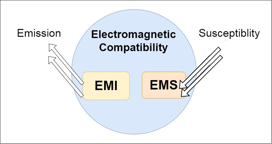
EMC stands for Electromagnetic compatibility, which means that a device is compatible with (i.e., no interference is caused by) its electromagnetic (EM) environment. It does not emit levels of EM energy that generate electromagnetic interference (EMI) in other devices in the vicinity.
Electromagnetic interference (EMI) is the interference caused by one electrical or electronic device to another by the electromagnetic fields set up by its operation.
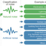
Sometimes we notice that the tube light is flickering when a water pump or motor device is on. This is because the motor draws more current, which causes a voltage drop. The change of electrical current and voltage generates electromagnetic interference (EMI). This interference must be within specific limits to avoid interference in the other devices present within the range.
An EMC test identifies this electromagnetic interference generated by a device. EMC tests also determine how the device reacts to electromagnetic interference caused by another device.
All devices have the potential to emit electromagnetic fields. The devices used in our daily lives such as TVs, mobile phones, washing machines, ATMs, RFID tags, etc., all generate electromagnetic interference or can be damaged by interference generated by another device. To ensure the proper functioning of devices, an EMC test performs several sub-tests on the equipment under test ( EUT) to test the immunity of the victim device to survive in an environment of electromagnetic emission. Also, the EMI generated by the EUT should be within the limit of interference regulated by the country.
Types of EMC tests
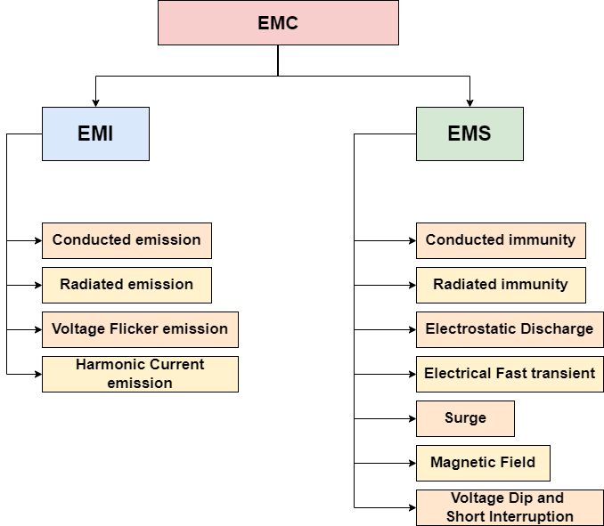
The basic block diagram of EMC tests is given below. Not all of these are not applicable for each product, and another test will likely be added according to the product’s application.
EMC tests are comprised of two tests—one is EMI (Electromagnetic Interference), and another is EMS (Electromagnetic Susceptibility).
Electromagnetic Interference (EMI)
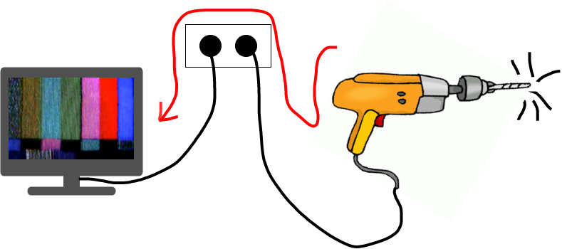
An electronic device will generate current and voltage fluctuations, which produce electromagnetic interference (EMI). Therefore, EMI generated by a particular device needs to be limited by the proper electronic design and shielding so as not to affect neighboring devices.
For example, a drill machine running in the house can cause TV flickering in the neighborhood house because they are connected with the same supply line.
Types of Electromagnetic Interference (EMI)
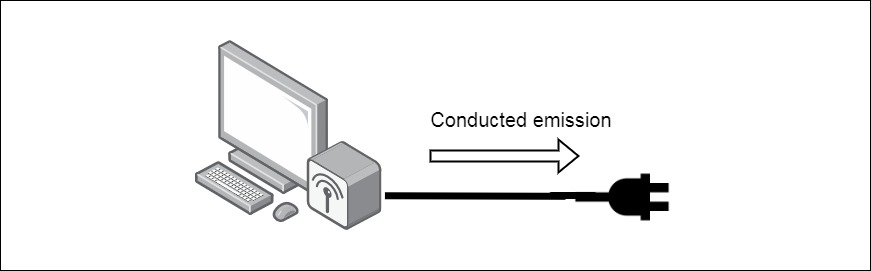
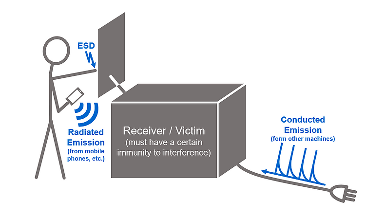
- Conducted Emission
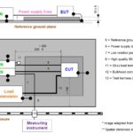
When the device emits an electromagnetic field and transmits it from the conductor of a wire, it is called conducted emission. It can potentially cause problems in the entire power distribution network, affecting other devices.
- Radiated Emission
When the device emits electromagnetic energy, it is released as electromagnetic fields that propagate through the air and can also interfere with other nearby devices.

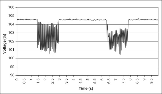
- Voltage Flicker Emission
Voltage Flicker occurs by changing load current, which flickers both frequency and amplitude. This can be illustrated by the change of a light bulb’s brightness or changing the speed of the motor or fan.
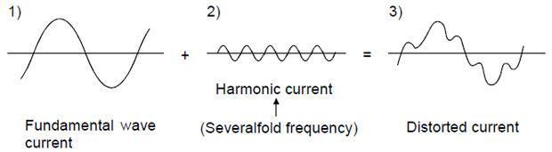
- Harmonic Current Emission
When the device emits any harmonics and distorts the mains supply, it is called harmonic current emission. It is associated with switch mode power converters and other non-linear loads such as motor, transformer, and lamp dimmers.
Electromagnetic Susceptibility (EMS)
Electromagnetic Susceptibility (EMI) means the device is capable or has immunity to survive or works as expected in an environment where other devices generate electromagnetic interference. Every device tends to emit electromagnetic interference, so the victim device should not misbehave in these environments; these are all noted in the EMS test standards of the country.
Let’s take a real-life example to understand why is EMS test is required. If a user hears any noise in their mobile while another mobile or any home appliance is in use, it is because of the low immunity of the device.

Types of Electromagnetic Susceptibility (EMS)
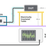
- Conducted immunity
In the conducted immunity test, the disturbance in cable or power supply is created by an RF amplifier, and the device’s function should not be affected by that distortion or interference in the power supply.
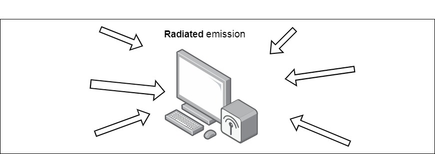
- Radiated immunity
In a radiated immunity test, the device creates an electric field disturbance, noise, or magnetic field interference through the air. In this scenario, the device should perform as expected.
- Electrostatic Discharge (ESD)
Electrostatic Discharge is the Discharge of the human body in the metallic part of the device; whenever the human body touches the device, they will get a shock. It could permanently damage the device, so that this test will check the protection and immunity against ESD.

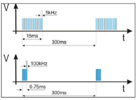
- Electrical Fast Transient (EFT)
The EFT immunity test simulates the switching of inductive loads in the real world. The inductive load switching creates a small spark, which is a bursting of pulses. The device must be able to handle those pulses.
- Surge
ESD and EFT have similar rise times, pulse width, and energy levels. With a surge, the pulse’s rise time is just 1.2us, and the duration is longer. The pulse width is 50us so there should be protection in the circuit to handle the surge.
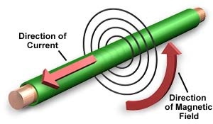
- Magnetic Field
The magnetic field is everywhere; a current passing through a wire can generate a magnetic field around the wire. In this test magnetic field is created to test the device’s behavior and the functionality of the device should not be affected.
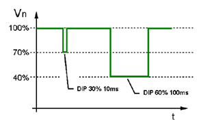
- Voltage Dip and Short Interruption
In this test, the power supply fluctuations are created in either AC or DC, and then the device is observed under these conditions.
Global rules and regulations
The EMC standard is different for every country. The Federal Communication Commission (FCC) has some regulations and standards for EMC certification in the USA. In Canada, Industry Canada is equivalent to FCC. In Europe, the CE mark is equivalent to FCC.
Some of the Marks provided by these regulatory bodies are as follows: