• Skip to primary navigation
  • Skip to main content
  • Skip to primary sidebar
  • Skip to footer

Analog IC Tips

Analog IC Design, Products, Tools Layout

  • Products
    • Amplifiers
    • Clocks & Timing
    • Data Converters
    • EMI/RFI
    • Interface & Isolation
    • MEMS & Sensors
  • Applications
    • Audio
    • Automotive/Transportation
    • Industrial
    • IoT
    • Medical
    • Telecommunications
    • Wireless
  • Learn
    • eBooks / Tech Tips
    • FAQs
    • EE Learning Center
    • EE Training Days
    • Tech Toolboxes
    • Webinars & Digital Events
  • Resources
    • Design Guide Library
    • Digital Issues
    • Engineering Diversity & Inclusion
    • LEAP Awards
    • Podcasts
    • White Papers
    • DesignFast
  • Video
    • EE Videos
    • Teardown Videos
  • EE Forums
    • EDABoard.com
    • Electro-Tech-Online.com
  • Engineering Training Days
  • Advertise
  • Subscribe

Unity gain amplifier or voltage follower in a voltage divider

May 5, 2017 By Janet Heath

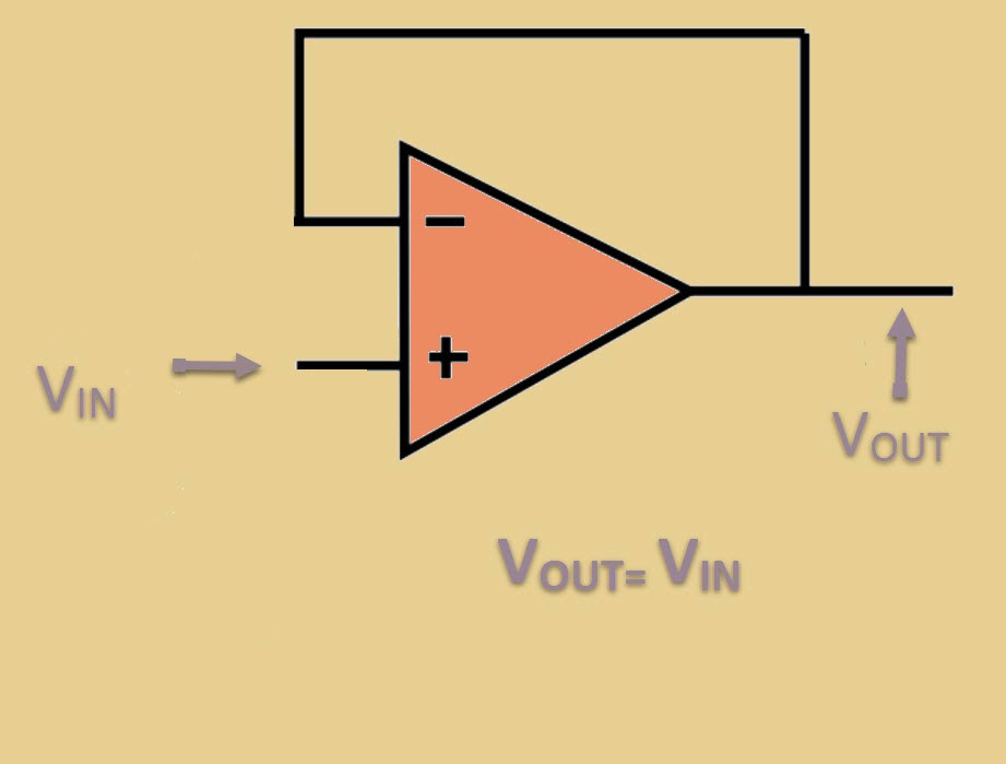
A voltage follower is also known as a unity gain amplifier, a voltage buffer, or an isolation amplifier. In a voltage follower circuit, the output voltage is equal to the input voltage; thus, it has a gain of one (unity) and does not amplify the incoming signal. The voltage follower does not need any external components. See Figure 1. But if it’s an amplifier and doesn’t amplify, what’s the purpose of a voltage follower?

unity gain amplifier
Figure 1: A voltage follower has a gain of one, so (theoretically) the output voltage is equal to the input voltage.

Operational amplifiers have a very high input impedance, which means that they don’t suck in much current (ideally, none) at the inputs. Op amps also have a very low output impedance. One application where this is useful is in a voltage divider. In a voltage divider (as in Figure 2), it’s possible that the impedance load (Ro) can vary quite a bit. Due to Ohm’s Law (V=IR), if Ro varies, it will affect VOUT.

Figure 2: A voltage divider, but as Ro varies, VOUT varies due to Ohm’s Law.


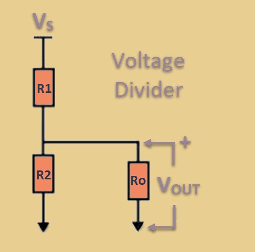
In Figure 2, if Ro varies, then VOUT would vary accordingly unless…. you were able to isolate the voltage divider’s VOUT by inserting a high impedance voltage follower between it and Ro, as in Figure 3. Adding a voltage follower to the voltage divider circuit isolates the load impedance (Ro) so that VOUT is dependent upon R1 and R2 (see figure 3), not Ro.

Figure 3: A voltage divider with a voltage follower (unity gain amp) that allows VOUT to remain steady.


This is only possible because the op amp has such a high input impedance and a low output impedance; the op amp works to maintain this state! (Remember that an op amp is a powered device, not a passive device. Op amp symbols rarely show the supply voltage to an op amp, but it’s always there when you actually hook one up.)

The voltage follower (Figure 1) allows us to move from one circuit to another and maintain the voltage level. It preserves the voltage source signal. This is why it’s also called a buffer or isolation amplifier. You can use a voltage divider circuit to switch from one logic level (e.g. 5V) to another logic level (e.g., 3.3V). A cleaner switch is obtained when a voltage follower (buffer amplifier) is added to the voltage divider circuit (Figure 3).  Another way to accomplish logic level shifting or translation is to use an IC called a level shifter to accomplish the same buffered transition. The high impedance of the op amp makes it possible for the voltage follower circuit to keep the load (Ro) from affecting the output voltage.

(Logic levels are used for binary signaling (HI/LOW), not for supplying power, so use a voltage regulator if you need to step down Power (P=VI) to a load. A voltage divider is not a regulator and you could end up smoking a resistor if a voltage divider is used to step-down a power source.)

With or without a voltage divider circuit, the voltage follower, or voltage buffer, offers a means to transfer a voltage source signal from one impedance level to another without affecting current. Ohm’s Law (V=IR) dictates the relationship from there. Voltage followers are used to match impedance in other circuits, too. Note that there is also a current buffer, which preserves the current signal source, rather than voltage signal source.

Filed Under: Amplifiers, Analog ICs, FAQ, Featured, Products Tagged With: basics, FAQ

Primary Sidebar

Featured Contributions

Design a circuit for ultra-low power sensor applications

Active baluns bridge the microwave and digital worlds

Managing design complexity and global collaboration with IP-centric design

PCB design best practices for ECAD/MCAD collaboration

Open RAN networks pass the time

More Featured Contributions

EE TECH TOOLBOX

“ee
Tech Toolbox: Internet of Things
Explore practical strategies for minimizing attack surfaces, managing memory efficiently, and securing firmware. Download now to ensure your IoT implementations remain secure, efficient, and future-ready.

EE LEARNING CENTER

EE Learning Center
“analog
EXPAND YOUR KNOWLEDGE AND STAY CONNECTED
Get the latest info on technologies, tools and strategies for EE professionals.

EE ENGINEERING TRAINING DAYS

engineering

RSS Current EDABoard.com discussions

  • Hard wired security cameras
  • Calculating inductor value for buck converter using XL1509 IC
  • i need an embedded c program that will read a 12 bit memory address from the io pins and output the data to pins from the memory in a 8051 mcontroller
  • Spice model for diode for rectifier simulation
  • Can I Flip Primary Connections on Mini-Circuits TCN1-10+ to Invert Output Polarity?

RSS Current Electro-Tech-Online.com Discussions

  • 12v battery, 18v magic
  • Back to the old BASIC days
  • Need help in repairing a dead motherboard
  • LED circuit for 1/6 scale diorama
  • how to work on pcbs that are thick
“bills

Design Fast

Component Selection Made Simple.

Try it Today
design fast globle

Footer

Analog IC Tips

EE WORLD ONLINE NETWORK

  • 5G Technology World
  • EE World Online
  • Engineers Garage
  • Battery Power Tips
  • Connector Tips
  • DesignFast
  • EDA Board Forums
  • Electro Tech Online Forums
  • EV Engineering
  • Microcontroller Tips
  • Power Electronic Tips
  • Sensor Tips
  • Test and Measurement Tips

ANALOG IC TIPS

  • Subscribe to our newsletter
  • Advertise with us
  • Contact us
  • About us

Copyright © 2025 · WTWH Media LLC and its licensors. All rights reserved.
The material on this site may not be reproduced, distributed, transmitted, cached or otherwise used, except with the prior written permission of WTWH Media.

Privacy Policy