Filters are essential functions in most circuits and systems; as frequencies extend into the multi-GHz range, surface acoustic wave (SAW) and bulk acoustic wave (BAW) filters are needed to meet the design objectives.
An engineer I worked with (and whose name I have forgotten) once remarked to about electronic filters (and he was serious): “like so many things, maybe you can’t live with them, but you certainly can’t live without them”. For many engineers, the entire subject of filters can be daunting. The topic encompasses so many technical issues such as Bode plots, poles and zeroes, passband and stop-band ripple, rolloff skirts, phase delays, and more. Plus, there are numerous topologies such as Sallen-Key, Butterworth, Chebyshev, elliptical, pi, (to cite just a few), providing low-pass, high-pass, band-pass, and notch/band-reject with a variety of tradeoffs, and all supported by advanced math and complex numbers. There are countless articles ranging from practical, hands-on filter discussions to intensely academic papers on the subject, and everything in between.
Why all this attention? It’s simple: filters are an essential functional block in situations ranging from low-frequency AC-line filtering to tightly spaced RF filters which sort out channels in the spectrum. This FAQ will look at a widely used yet special class of filters which use surface acoustic wave (SAW) and bulk acoustic wave (BAW) technologies.
Q: What are the traditional ways to create a filter?
A: There are several:
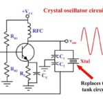
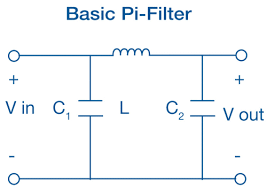
- All-analog filters use “lumped” discrete components (resistors, inductors, capacitors), and have been the subject of math analysis, models, simulation, construction, and widespread use. These filters can be totally passive or use active components (primarily op amps) for gain and other attributes. They are the oldest class of filter and can range from a simple R-C high- or low-pass design to complex, multipole constructs. They can be used from near DC into the hundreds of MHz and even GHz (more on this below) (Figure 1). These are sometimes called “continuous-time” filters.
- Switched-capacitor filters work by transferring charge into and out of capacitors as internal switches are opened and closed by an external clock (Figure 2).
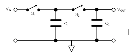
- Their performance depends only on the ratios between capacitances, which makes them very suitable for implementation as part of a monolithic IC due to process compatibility. These filters are “cousins” to the switched-capacitor voltage-boost circuit (Reference) except that for those circuits, the input is a DC voltage, while in the switched-capacitor filter it is an AC waveform which can range from low frequency up to about 1 MHz maximum
- Digital filters, as the name indicates, operate on the sampled, digitized values of the signal and execute numeric calculations implementing filtering algorithms on that data (Figure 3.
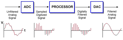
- In many cases, they replace physical-component filters with an just A/D converter and the processor (general purpose or numeric engine optimized), and so save BOM cost and space an PC board space; they can also implement filter structures which simply cannot be realized with physical components. The practical upper limit for such a filter is several MHz, due to the demands they place on the A/D converter and the processor. They are sometimes called sampled-data or discrete-time filters for obvious reasons.
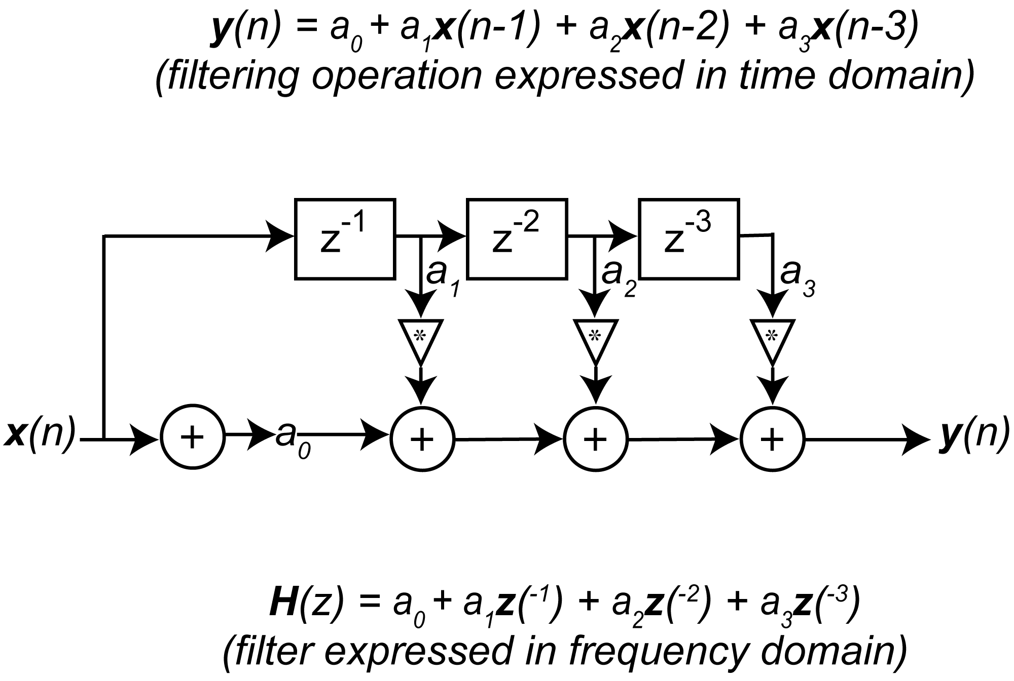
Digital filters are also used extensively in sigma-delta A/D converters to filter the one-bit sampled stream and produce useful results. In these cases, the digital filter is not implemented as a series of program steps to be executed by a processor. Instead, it is realized as a series of tapped delay stages with pre-defined weightings to execute a filtering equation (Figure 4).
Q: Why all this attention to filters?
A: Filters have been an essential building block in almost every electronic system, where power, audio, measurement and control, RF, and more – and the need for them is growing. They filter out 50/60 Hz line noise, offending signal, noise, and nearby channels, improve SNR,….it’s a long list.
Q: What are the technical problems with filters?
A: There are many beyond their theoretical limitations. Among them are component tolerances, unavoidable parasitics (which have a greater effect as the frequency increases), and drift due to temperature coefficient. In addition, there is board space required and BOM cost. In many cases, the filters have to be individually tuned and trimmed due to these imperfections, and they may still be inadequate.
The three filter types cited tend to be very difficult, and costly to create as frequencies reach hundreds of MHz and into the GHz range and the performance demands increase as well, although it has been done with all-analog filters for many years.
Part 2 of this FAQ will look at a widely used filtering technique and component implementation which leverages electronics, the piezoelectric effect, and acoustic waves to provide tiny, low cost, highly effective filtering for frequencies from hundreds of MHz and into the multi-GHz ranges.
References
- EE World, “Bulk acoustic wave filters make life easier for Wi-Fi front-end designers”
- EE World, “Radio receiver architectures, Part 1—TRF and Superhet”
- EE World, “FAQ: Piezoelectric motors, Part 1: actuators”
- EE World, “Quartz crystals and oscillators, Part 1: Crystal basics”
- EE World, “Working with higher voltages, Part 1: Voltage boosters”
- Texas Instruments, Application Note SNAA326, “How to use the LMK05318 as a jitter cleaner”
- Wikipedia, “Crystal filter”
- Wikipedia, “Piezoelectricity”
- Qorvo, “RF Filter Technologies”
- Qorvo, “Bulk Acoustic Wave (BAW)”
- API Technologies, “Introduction to SAW Filter Theory & Design Techniques”
- CS Mantech Conference, “Bulk Acoustic Wave Devices – Why, How, and Where They are Going”
- Broadcom, “FBAR Devices”
- Microwave Journal, “SAW/BAW New Market Entrants Offer New Approaches“