Part 1 of this FAQ looked at the basic available electronic filters – analog, switched capacitor, and digital – and briefly reviewed the attributes of each. As the frequencies to be filtered reach to 1 GHz and well beyond, while the selectively needed also became narrower, these filter approaches can no longer support many of the requirements.
Fortunately, there are two alternatives, both based on the piezoelectric effect but using it in very different constructs. This FAQ will explore the surface acoustic wave (SAW) and bulk acoustic wave (BAW) filters, which are widely used for Wi-Fi, smartphones, and the newer 5G standard, to cite a few applications.
Q: Remind me, what’s the piezoelectric effect?
A: It’s a dual phenomenon of physics which was explored in the late 1800s by many scientists, but had little practical application until the development of radio in the early 20th century. In brief, it shows that a crystal substance — initially quartz, but now many other “manufactured” materials — will generate electricity when put under mechanical stress, and the reverse is true as well: the crystal will stretch by a tiny amount when an electric field (voltage) is applied. In other words, piezoelectric materials convert applied mechanical stress into electrical energy and can also transform electrical energy into mechanical strain.
Q: How it is used?
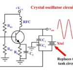
A: The piezoelectric (“piezo”) effect is widely used. Quartz crystals are used as the frequency-control elements in oscillators; to generate waveforms at MHz frequencies for ultrasound transducers, highly precise linear motors, and even to create sparks which can ignite a flammable gas. It is a long list of their applications where they are used for electrical to mechanical energy conversion or its complement.
Q: So how is the piezo effect used for electrical filtering? Is doing so a new development?
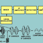
A: The use of electromechanical resonance of a crystal to create a precision bandpass filter, with the resonant frequency determined by the physical dimensions as well as the crystal’s properties is not new. In the 1930s and 1940s, they were used for narrowband IF filters in superheterodyne radios. In many radios (including broadcast FM band), the IF frequency was standardized at 10.7 MHz and crystal filters for that frequency became a wildly available component.
Q: How can crystals be used for filtering at GHz and higher-frequency filtering?
A: The basic idea is to use the piezo material to transform the RF energy into mechanical motion, and have it carried as acoustic wave via the piezo material, then transform it back to electrical energy. The electrical/mechanical and mechanical/electrical transducers are electrodes deposited in the appropriate location and shape on the piezo material.
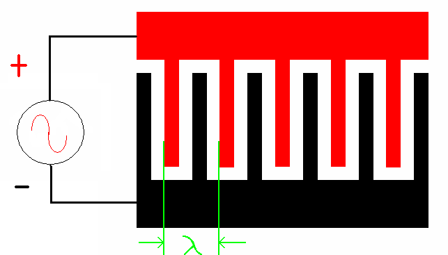
Q: What does the SAW filter look like?
A: The acoustic waves travel through the interleaved metal “fingers” of interdigital transducers (IDTs) fabricated on the surface of the piezoelectric substrate. This substrate is usually lithium tantalite (LiTaO3, lithium niobate (LiNbO3), or quartz crystal. The periodic interdigital electrodes connect to two electrodes (Figure 1), and the wavelength λ of the electrodes and neighboring spaces determines the operating frequency of the device.
Q: How is this fabricated?
A: It’s done similarly to IC fabrication — usually on relatively large piezoelectric wafers with diameters of 8 to 12 inches (20 to 30 cm).
Q: Besides filtering, for what else can a SAW device be used?
A: Because the acoustic wave travels along the piezo surface much more slowly than an electronic signal in wires, the SAW device can be used for a delay line. Such delays are needed in many applications, such as to synchronize data in communications systems or correlate a transmitted radar signal with its echo return. SAW devices can typically provide delays of 0.1 to 10 µsec.
Q: How small are SAW devices? What are their primary performance characteristics?
A: Size is a function of frequency and packaging, of course, but they are small and available in standard, tiny IC packages. For example, the SF0266CN02358S from Spectrum Microwave is a 266.667 MHz SAW bandpass filter with 0.27 MHz bandwidth housed in a 7 × 5 mm LCC package.
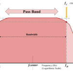
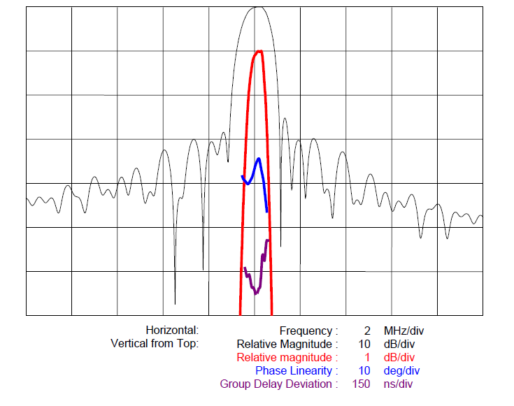
As with all filters, primary considerations are center or edge frequency and bandwidth, along with rolloff, insertion, selectivity, Q (quality factor) loss, and phase shift, among other parameters. The top-tier performance factors are illustrated in Figure 2.
Q: What is the useful frequency range of SAW devices?
A: They are practical from about 30 MHz to 1500 or 2000 MHz (1.5 to 2 GHz).
Q: Then what? Is the use of piezo-based filters over?
A: Not at all. Another piezo-based approach is used, called the bulk acoustic wave filter.
Q: How does it differ from the SAW filter?
A: In a BAW component, the acoustic waves travel and are stored within the piezoelectric material rather than across the top surface of the substrate as they do in a SAW device
Q: How are BAW devices fabricated?
A: BAW components are also fabricated on piezoelectric materials, although typically using different substrate materials than their SAW counterparts. The metallization of the electrodes is deposited on the top and bottom of the piezoelectric material, which creates an acoustic “channel” for the energy waves. The waves then resonate within the material between the metal layers and through the piezoelectric material (Figure 3). The resultant standing wave has a resonant frequency which is a function of the substrate thickness and the mass and type of metallization (thinner substrates yielding higher operating frequencies).

Q: Are there different BAW designs?
A: Yes, There are two common configurations of BAW architectures: the film bulk acoustic resonator (FBAR) and solidly mounted resonator (SMR). The very widely used FBAR has free surfaces on both sides of the BAW resonator, while the SMR structure substitutes the free surface on the bottom of the resonator with an acoustic Bragg reflector.
Q: What is the frequency range of BAW devices? What about available delays?
A: The frequency ranges from about 1.5 GHz to 15 GHz, which overlaps nicely with SAW devices. Available delays are in the range of 0.15 to 3000 µsec.
Q: Do BAW and SAW components use the same substrate and electrode materials?
A: Generally not. The most common BAW material is aluminum-nitride (AlN). The electrode material depends on operating frequency and power level. It can be aluminum or even tungsten for higher-power devices
Q: What are the power ratings of SAW and BAW devices?
A: It varies, of course, but they range from several hundred milliwatts to several watts, depending on size, frequency, and packaging.
Q: Who makes these filters?
A: There are many vendors. Some specialize in only a narrow frequency range or type, some only make SAW devices or only BAW devices, and some make both types and devices for a wide range of frequencies.
This FAQ has looked at the fundamentals of filter technologies beginning with the analog filter, then proceeding to switched-capacitor and digital filters. It has also examined SAW and BAW filters, which are essential for modern RF devices due to their excellent performance, small size, packaging, low cost, and other attributes for the >1 GHz regions.
References
- EE World, “Bulk acoustic wave filters make life easier for Wi-Fi front-end designers”
- EE World, “Radio receiver architectures, Part 1—TRF and Superhet”
- EE World, “FAQ: Piezoelectric motors, Part 1: actuators”
- EE World, “Quartz crystals and oscillators, Part 1: Crystal basics”
- EE World, “Working with higher voltages, Part 1: Voltage boosters”
- Texas Instruments, Application Note SNAA326, “How to use the LMK05318 as a jitter cleaner”
- Wikipedia, “Crystal filter”
- Wikipedia, “Piezoelectricity”
- Qorvo, “RF Filter Technologies”
- Qorvo, “Bulk Acoustic Wave (BAW)”
- API Technologies, “Introduction to SAW Filter Theory & Design Techniques”
- CS Mantech Conference, “Bulk Acoustic Wave Devices – Why, How, and Where They are Going”
- Broadcom, “FBAR Devices”
- Microwave Journal, “SAW/BAW New Market Entrants Offer New Approaches“