
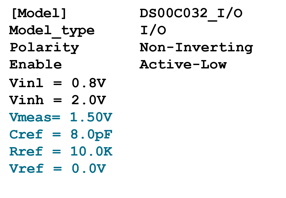
An Input Output Buffer Information Specification (IBIS) model is a standard in the semiconductor industry for modeling semiconductor devices from a behavioral perspective, for both analog and digital perspectives. IBIS modeling enables engineers to describe detailed signal behavior in a circuit design without revealing proprietary information about the circuits (or the processes used to make them). Simulation Program with Integrated Circuit Emphasis (SPICE) is another model simulator. Both IBIS and SPICE are able to simulate, analyze, and provide feedback on the performance of a circuit design. However, the two model simulators are different. IBIS is a behavioral model, whereas SPICE is a structural model. Circuit simulation is a critical component in the design of electronic circuits. One of the most popular uses for IBIS is as a tool to analyze the signal integrity of system boards. Technically speaking, IBIS models I/O buffer behavior based on V/I (voltage/current) curve data that is derived from full circuit simulation (typically on SPICE) and actual bench measurements. V/I curves represent the relationship between voltage and current as it affects device, circuit, or certain materials.
Simulation models greatly facilitate detailed signal integrity analysis, as engineers can test the impact of design changes or determine whether a final design is ready to become an actual, physical prototype. A critical tool to knowing how a signal looks while propagating a trace, IBIS models enable a view into what might happen as the signal confronts changes in impedance, vias, stubs, terminations, and other signal path geometries that can alter intended signal characteristics. Signal integrity analysis investigates problems common to circuit design such as overshoot, undershoot, crosstalk, ringing, impedance mismatch, reflection, termination issues, analysis of different topologies, among other things.
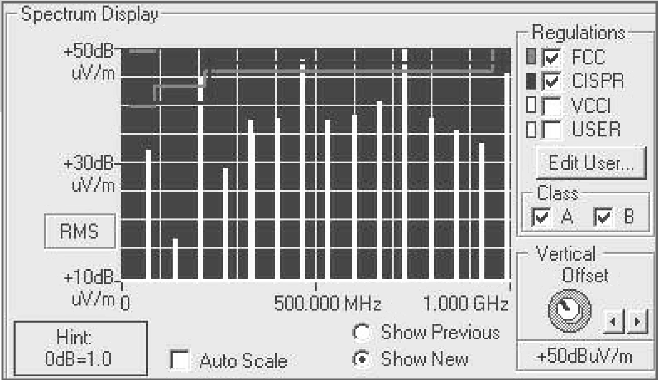
IBIS models can model best- or worst-case scenarios (and everything in between) by employing maximum or minimum values. These standardized-format models play a part in circuit simulators (e.g., SPICE) by providing characteristics that are unique to a given integrated circuit. Detailed IBIS models enable more realistic simulations and are especially beneficial for the computer modelling of numerous test conditions that stem from non-ideal consequences. Thus, IBIS models help to incorporate real-world issues into boards before they are first prototyped, such as parasitic capacitance associated with different layouts and packages, trace termination, identify the potential perils of Electromagnetic interference (EMI), and much, much more. Another benefit to IBIS models is that they can be easily created using the results from bench measurements as well as simulation data.
When steady-state and transient responses can be simulated before boards are manufactured, and even before first silicon comes off the pilot line at the semiconductor manufacturer’s factory, engineers can better meet time-to-market requirements. As soon as the new integrated chip is available, it gets soldered into the board for the test bench. This way, all ports, peripherals, and test points can be exercised within days or hours of the first silicon’s trip to packaging.
IBIS models are supported by almost every Electronic Design Automation (EDA) tool in the industry, and dominant manufacturers in the industry support the IBIS standard by participating in the IBIS open forum. IBIS model generation is standardized and fostered amongst participants in the forum to encourage 100% compatibility, even backwards compatibility, of IBIS models and their validation.
Some pitfalls associated with models is that even when comparing apples-to-apples (e.g., NAND gate-to-NAND gate, or similar components or structures) not all manufacturers will provide the same data in their models. This makes it difficult to compare features between similar components. Those creating models may not realize how end users may use their models. The IBIS open forum works to bring those who develop the IBIS models, the EDA tool makers, and end users together for creating a standardized IBIS model for the common good of all.
A term that should be familiar within IBIS model developer community is “the Golden Parser.” This is a free test to check if the ASCII (IBIS) model (that the developer has newly created) has the proper syntax that conforms to the specification. The golden parser, with versions available for several operating system platforms, is free on the IBIS website.
Electricity behaves differently (versus what most of us are familiar with) in transmission lines, ground planes, at high frequencies, and AC versus DC. Models and the EDA tools (simulators) to run them are also indispensable in developing an understanding, or intuition, of how electricity behaves in less-than-typical scenarios. Although simulations are never as good as the real thing, learning from EDA tools is a fast way to develop that intuition that comes from experiencing repeated trial and error.
To learn more about IBIS models, check out the reference list below.
Introduction to IBIS Modelling (PDF) by Texas Instruments
The IBIS model: A conduit into signal integrity (PDF) by Texas Instruments
IBIS.org Articles: a list of related articles.
Chapter 10 in Perfect Timing II (PDF) by Cypress Semiconductor (3.14 MB)