The lower-frequency world of electronic circuits and systems for communications links routinely uses parameters such as voltage and current, bit rates, and signal/noise ratio, to cite just a few of many, many possibilities. While these are also important in the world of RF and microwave links and system functions, engineers doing work in this arena also focus on power, impedance and matching, and two noise-related parameters: noise factor (and figure) and noise temperature. This FAQ will explore the meaning, role, and utility of these two figures of merit.
Q: Why is “noise factor” (F) needed?
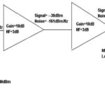
A: Noise and noise factor is used to characterize both the overall system as well as the components in the signal chain, such as preamplifier, mixer, amplifiers, filters, and other circuit-path blocks (oscillators, for various reasons, have a different primary figure of merit). It defines the system floor in terms of system sensitivity and the level below which received signals cannot be recovered as noise overwhelms the desired signal, Figure 1. Any noise added by a gain block (as they all add noise) raises signal level but decreases SNR.
Q: What does noise factor (F) represent?
A: The dimensionless quantity F is th ratio of two other ratios: the signal-to-noise power ratio at the Input of a device under test (DUT), which can be a single component or a larger subsystem, to the signal-to-noise power ratio at the output; in other words, it is the ratio of two well-known ratios. It shows how much noise is added by that component or function, whether it is an RF transistor, preamplifier or low noise amplifier (LNA), or gain block. It is generally independent of the signal level within a linear operating region, as it is the noise added, rather than the absolute noise level or noise power.
Q: Is that all there is?
A: Of course not; nothing in electronics, especially the RF/microwave world is ever that simple. The Internal noise is a function of device physics, of course, but also thermally-induced random noise which starts at the atomic level. For this reason, the NF is highly dependent on the temperature at which it is measured or the system is used. The reduction in a network’s signal-to-noise ratio is a function of the temperature of the source that excites the two-port network (input vs output).
Further, noise power is a function of bandwidth: wider bandwidths allow more noise in the system. For that reason, the noise factor must use the same input and output bandwidths, so the bandwidth-induced noise-power difference cancels itself out.
Q: So how do we come up with a meaningful way to define noise factor?
A: RF experts of all sub-disciplines have studied this problem from theoretical and practical perspectives since the beginnings of the 20th century, when “wireless” and use of higher frequencies were beginning to take on larger roles, needed to be quantified, and their limitations needed to be understood. Without going into the derivation or rationale, the definition begins with the input noise level (which is usually due to thermal noise from the source and is referred to by kT0B), using a reference source temperature of 290 K denoted by T0, (equivalent to 16.8°C and 62.3°F). The quantity kT0 is called power spectral density band equals 4.00 × 10⁻²¹ watts per hertz of bandwidth (–174 dBm/Hz).
Q: Where does this lead?
A: It culminates in the industry-standard definition of noise factor F:
F = (NS + kT0BG) / (kT0BG)
where k is Boltzmann’s constant (1.38 x 10⁻²³ joules/K), T is the temperature in K, and B is the system’s noise bandwidth.
Q: What is the unit associated with noise factor F?
A: It can be expressed as a ratio, of course, but it is almost always expressed as noise figure, which is a logarithm (dB):
NF (in dB) = 10 log F
Q: What are the key “takeaways” of this noise discussion?
A: There are several:
–the noise factor and noise figure of a DUT represents the degradation of the SNR as an input signal passes through the DUT;
–the input noise level for assessing that degradation uses a 290 K source temperature as its reference.
Q: How do we avoid confusion in terminology between noise figure F and noise figure NF in dB?
A: It’s general industry practice to use the term “noise factor” or “noise figure in linear units” for the non-dB ratio, and “noise figure” for the dB value.
Part 2 of this FAQ will look at the related factor of noise temperature, as well as making and applying noise-related measurements.
References
- Keysight Technologies, “Fundamentals of RF and Microwave Noise Figure Measurements”
- National Instruments, “Noise factor, noise figure, and noise temperature”
- IEEE Microwaves 101, “Noise Temperature”
- Sujeong Lee, “Noise Power, Noise Figure, and Noise Temperature”
- Satellite Signals Ltd, “Noise temperature, Noise Figure (NF) and noise factor (f)”
- QSL Net, “Understanding Noise Figure”