
Power management encompasses a range of power converter types and topologies and includes systems like ac/dc power supplies, dc/dc converters, LED lighting, and battery chargers. Designing compact, cost-effective, and efficient power management systems is challenging and requires a combination of skills in high voltage and high current design, control loop optimization, mitigation of electromagnetic interference […]
keysighttechnologies
Semiconductor device modeling software adds model generator environment
Keysight Technologies, Inc. announced a new model generator (MG) environment that increases productivity for semiconductor device modeling engineers with improved automation across the entire workflow. Semiconductor device modeling engineers require automated tools to create accurate simulation models and process design kits (PDK) for baseband and radio frequency (RF) integrated circuit (IC) designs that leverage both silicon (CMOS) […]
Simulate, test, and verify to solve 5G RF design problems

Performing these three steps can improve mmWave and beamforming performance.
What are the applications and measurements of S-parameters? Part 2
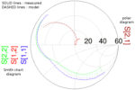
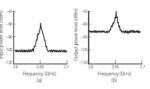
Part 1 of this FAQ was a basic introduction to the context and concept of S-parameters. Part 2 looks at their measurement, application, and relationship to the time domain. Q: How do you actually measure S-parameters? A: In general, except for approximate measurements, you cannot use a spectrum analyzer alone for this frequency-domain test. Instead, […]
What are the functions and principles of S-parameters? Part 1
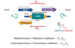
As design frequencies now routinely go into the hundreds of MHz and tens of GHz range, conventional voltage and current measurements are not useful. However, scattering (s) parameters can fully characterize the RF component or path performance. For engineers with experience focused from DC to several hundred megahertz, it is usually sufficient to characterize components […]
RF switches, Part 2: Analog and MEMS switches
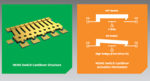
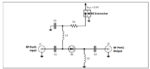
Part 1 of this FAQ looked at the venerable electromechanical RF switch – still widely used in some applications, where it is the only viable option—and the use of PIN diodes as RF switches. This part looks at analog and MEMS-based switches. Q: What is an analog switch? A: It’s conceptually straightforward: in basic form, […]
RF switches, Part 1: Mechanical and PIN-diode switches
There’s a ubiquitous and increasing need to switch RF signals ranging into the tens of GHz; four basic switch technologies – electromechanical, PIN diode, analog, and MEMS – are available, each with different features and capabilities. The need to switch RF signals has been a necessary design function since the earliest days of “wireless.” This […]
RF/microwave noise, Part 1: Noise figure basics
The lower-frequency world of electronic circuits and systems for communications links routinely uses parameters such as voltage and current, bit rates, and signal/noise ratio, to cite just a few of many, many possibilities. While these are also important in the world of RF and microwave links and system functions, engineers doing work in this arena […]
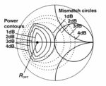
Load pull for RF devices, Part 2: How and where
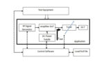
Part 1 of this FAQ explained the what and why of load-pull tests of RF devices and impedance matching. Part 2 looks at various ways the test can be set up and run. Q: What’s the basic test setup for a modern load pull? A: As shown in the figure of Part 1 (and repeated […]
Load pull for RF devices, Part 1: What and why
Impedance matching between RF stages has always been a priority to ensure maximum transfer of RF power along with minimal RF-power reflections. Although most RF systems are designed for nominal 50-ohm input and output impedance (and 75-ohm for cable TV), the reality is that many components do not present that preferred 50-ohm impedance due to […]