There’s a ubiquitous and increasing need to switch RF signals ranging into the tens of GHz; four basic switch technologies – electromechanical, PIN diode, analog, and MEMS – are available, each with different features and capabilities.
The need to switch RF signals has been a necessary design function since the earliest days of “wireless.” This switching may be within a circuit to route signals, to send (and receive) signal to (and from) one antenna out of many, or for a test matrix. Now, there’s also an increasing need for RF switching for new mass-market applications such as MIMO and beamforming for 5G, in addition to older uses in phased-array radar, for example.
This FAQ will look at the four major technologies used for RF switching, their key attributes, and their major characteristics. These four are the electromechanical switch, the PIN diode, the analog RF switch, and the MEMS-based switch.
Q: What are the top-tier performance parameters for RF switches?
A: In addition to the usual concerns about power consumption (if any), size, long-term reliability, and weight, designers are concerned about:
–Bandwidth, which can reach from low MHz or even DC to GHz and tens of GHz, along with flatness of spectrum performance across the bandwidth;
–VSWR (voltage standing wave ratio): ideally is unity, but under 2.0 is usually acceptable;
–Insertion loss: how much of the RF signal energy is lost is transitioning through the switch, in dB;
–Isolation: by how many dB are the switch input and input signals are separated when the switch is “off”;
–Power handling: how much power can the switch can handle, which is an issue for transmit-side switches, but not for receive-side signal paths;
–Configuration: some switches are basic on/off (SPST), others are SPDT, while others have multiple poles and can switch among many signal paths;
Q: What are electromechanical switches?
A: As their name indicates, this oldest of switch technologies uses direct metal-metal contact and is simplest in concept. It’s perhaps somewhat surprising that despite their size and the subtleties of RF signal paths – which ranges from smaller than a deck of cards to large boxes, depending on power levels – that they can provide excellent RF performance into the tens of GHz. These switches include integral coaxial connectors for ease of signal connections.
Q: Are electromechanical switches obsolete?
A: Despite their age and electromechanical nature, they are not at all obsolete, and are still the most viable option for switching higher-power RF signals. Switches are available which are manually operated or with the position set by a relay or motor and controlled via basic logic levels or even USB interface. As just one example out of the available thousands, the K2 Series of SPDT electromechanical switches from Microwave Communications Laboratories, Inc, operates from DC-26 GHz, comes with SMA connectors, and is controlled by a 28 VDC signal, Figure 1, with RF performance as a function of frequency, Figure 2. The isolation and insertion-loss specifications are impressive.


Q: Are these switches hard to find?
A: There are dozens of vendors for these switches, and variations are available to handle just one SPST or SPDT closure to multiple-contact versions needed for matrix routing, and at power levels from several watts to kW. They provide excellent RF performance, with an insertion loss of a fraction of a dB and isolation of >40 dB across their operating frequency band. A well-designed switch can operate to specifications for five to ten million cycles; the number of cycles is somewhat dependent if it is used as a hot switch (switching on/off with a signal present) or cold switch (no signal present during the switching cycle).
Q: What is the PIN diode RF switch?
A: The PIN diode is a special diode which can be configured as an RF switch. It has a wide, undoped intrinsic semiconductor region (“I”) sandwiched between a p-type semiconductor (“P”) and an n-type semiconductor region (“N”), hence the PIN designation. This is unlike a standard diode which has no intrinsic region. (Note that PIN diodes are also used as light-sensitive photodiodes, but that’s a different application, of course).
Q: What is the transfer function of the PIN diode, so that it can be used for RF switching?
A: A PIN diode functions as a conventional diode rectifier at low frequencies. However, at microwave frequencies, its IV curve changes and it functions as a current-controlled resistor, with the resistance value set by the level of DC current. Thus a PIN diode is a DC-controlled high-frequency resistor, and if no DC current is present, the diode is just like an open circuit.
Q: What is the frequency range of the PIN diode as an RF switch?
A: It is primarily a function of the thickness of the I-region, and thicker diodes can operate down to 1 MHz, while thinner ones can function into the multi-GHz range. Note that unlike an electromechanical RF switch, the PIN diode cannot operate down to DC.
Q: What’s the control-current versus power-handling ratio for PIN diode? What about switching speed? Isolation? Insertion loss?
A: The ratio is fairly high: just a few milliamps of DC current can allow the PIN diode to “short out” an amp or more of RF current, which is a significant amount of power in many RF applications. Switching speed is in the one microsecond and faster range, and isolation is in the 40 to 60 dB range. Insertion loss is low, as the forward-based RF resistance is about 1 ohm.
Q: What are the challenges of designs using the PIN diode?
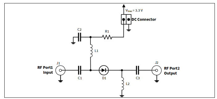
A: The major challenge that it is a two-terminal device, so the control signal (the DC bias) and the RF signal share the same terminals. This means they must be combined before they go to the diode, then separated afterward. Doing so requires a circuit topology which uses inductors and capacitors to separate the signals, and their values are somewhat tricky to determine, as they are a function of frequency, bandwidth, diode characteristics, layout parasitics, and more, Figure 3. For this reason, many vendors offer PIN-diode RF switches as complete modules with all supporting circuitry already included to greatly simplify the challenge.

Part 2 of this FAQ will look at newer devices for RF switching: the analog switch, and the MEMS-based switch.
References – EE World
- Specialized diodes, Part 2: Varactor, Gunn, and PIN diodes
- SPDT PIN Diode Switches cover 10 MHz to 67 GHz range
- High-power SPDT RF switches handle up to 6 GHz
- High-throw count RF switches span 9 kHz – 8 GHz range
- FAQ: What is a charge pump and why is it useful? (Part 1)
- FAQ: What is a charge pump and why is it useful? (Part 2)
- Working with higher voltages, Part 1: Voltage boosters
References – General
- Wikipedia, “RF Switches”
- Microwave Communications Laboratories Inc, “Electromechanical Switches”
- Skyworks Solutions, Inc, “PIN Diode Basics”
- Microsemi Corp, Micronote 701, “PIN Diode Fundamentals”
- Keysight Technologies, “RF & Microwave Electromechanical Switches”
- pSemi Corp/Murata, PE42412 Data Sheet
- Analog Devices, ADRF5046 Data Sheet
- Analog Devices, ADGM1304 Data Sheet
- Analog Devices, “MEMS Switch Technology: Breaking New Ground”
- Analog Devices, “The Fundamentals of Analog Devices’ Revolutionary MEMS Switch Technology”
- Analog Devices, ”Analog Devices Makes MEMS Switch Technology a Commercial Reality”
- Infineon, “PIN diodes in RF switch applications”


