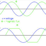
Inductors only behave like inductors below because of what’s called their self resonant frequency. And the self resonant frequency arises because the equivalent circuit of real-world inductors isn’t strictly inductive. There are parasitic elements that come into play.
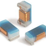
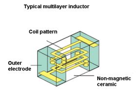
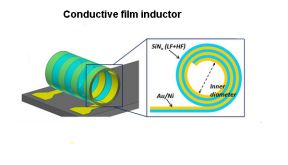
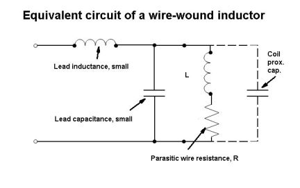 To understand why, look at the equivalent circuit for an inductor. An inductor can be comprised of coils of wire, or it can be what’s called a multilayer device, or it can be made with conductive films. All these have equivalent circuits that are similar. For simplicity, consider inductors made with coils. Their wire leads introduce a series inductance and capacitance that is in parallel with the ideal inductance. Wire-wound inductors also use a relatively large amount of wire in the coils, and the wire itself has a parasitic resistance modeled in series with the ideal inductance. Finally, there’s a parasitic capacitance in parallel with the series combination of the parasitic resistance and the ideal inductance. This capacitance arises mainly because the individual turns of the coil are in close proximity to one another. But if the inductor sits over a ground plane then there’s a capacitance between the inductor and the ground plane, and that is in parallel with the ideal inductance as well.
It turns out you can usually ignore a lot of the parasitic elements. The lead inductance is typically much smaller than the ideal inductance. And the lead capacitance is typically much smaller than the parasitic capacitance from the wire turns. Usually, the only time the parasitic resistance comes into play is at low frequencies or at dc when there are significant currents involved.
In many cases, the only parasitic element of interest is the capacitance between the coils themselves. But eventually, the parasitic capacitance of the coils has an effect. As frequencies rise the impedance of the parasitic capacitance drops until its magnitude equals that of the ideal inductance. The point where this happens is called the self resonant frequency. Here the impedance of the equivalent circuit is a maximum.
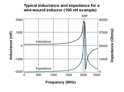
An example for one particular 100-nH coil reveals what typically happens. There is a huge impedance peak at the self-resonance frequency. Above the self-resonant frequency, the parasitic capacitance begins to dominate the behavior of the equivalent circuit. In this range of operation, the impedance drops with rising frequency. That’s where the inductor stops behaving like an inductor and more like a capacitor.
Inductors that are used as RF chokes or blocks are specified so they operate at their self-resonant frequency. The inductor operates like a tank circuit at that frequency and blocks frequencies at that point from passing. In the case where a circuit is designed to block a band of frequencies, rather than just that of the inductor self-resonant frequency, there is more than one inductor involved. Here the calculation of inductor elements generally takes place using commercial circuit simulation programs such as Spice or Keysight Technologies’ Genesys RF software.
Of course, when the inductor operates as something other than a choke, it is usually desirable that its inductance remains relatively flat vs. frequency over the expected range of operating frequencies. Thus designers should specify the inductor so its self-resonant frequency is well above the design frequency. Specifically, the rule of thumb is to select an inductor so its self-resonant frequency is a decade (10×) higher than the operating frequency.
Finally, the topic of tolerance and the amount of electrical current in the circuit can be important for tuned circuits or inductor self-resonance. Wire-wound inductors typically have tighter tolerances than multilayer or thick film-type devices.
Generally, wire-wound inductors handle more current than multilayer inductors of the same size and inductance value. And higher currents require the use of an inductor having a larger wire diameter to minimize losses and temperature rise. A larger wire lowers the dc resistance but at the expense of bigger parts and possibly a lower self-resonant frequency.
To reduce the dc resistance for a given value of inductance, the inductor might incorporate a ferrite core. Ferrite, though, tends to make inductance vary more widely with temperature. And ferrite-core inductors have looser tolerances than those that do not.
References
Coilcraft Inc., http://www.coilcraft.com/
University of Ill. Film inductor paper