Sensor fusion is increasingly important across a range of applications including automotive, industrial, consumer, portable, medical systems, and others. It can be challenging to sort out the design issues and identify the optimal solution. That’s where electronic design automation (EDA) tools are handy. The best choice of EDA tool or tools for a given project depends on several factors like what’s already available in the development lab, how complex the integration challenges are, and so on.
This first of two FAQs looks at two sources for EDA tools, component suppliers, and general-purpose EDA software vendors along with a few exemplary tools for a variety of sensor technologies. These FAQs are not intended to be exhaustive but rather to provide “food for thought.” Part two will present EDA offerings from specialist tool makers.
Proximity sensors, current sensors, and accelerometers
Component suppliers are often a good source for sensor modeling and system development tools. First up is the Hall-Proximity Design tool from Texas Instruments. This software supports iterative design of magnetic and Hall-effect sensor applications. Key features include:
- Inputs for magnet specifications and relative locations of the magnet and sensor.
- Tools for filtering devices based on operating voltage and sensor type.
- Plot of magnet displacement versus magnetic field.
- Output with respect to magnet displacement from sensor plot.
- Operating point (Bop) and release point (Brp) displacement distances for switches and latches
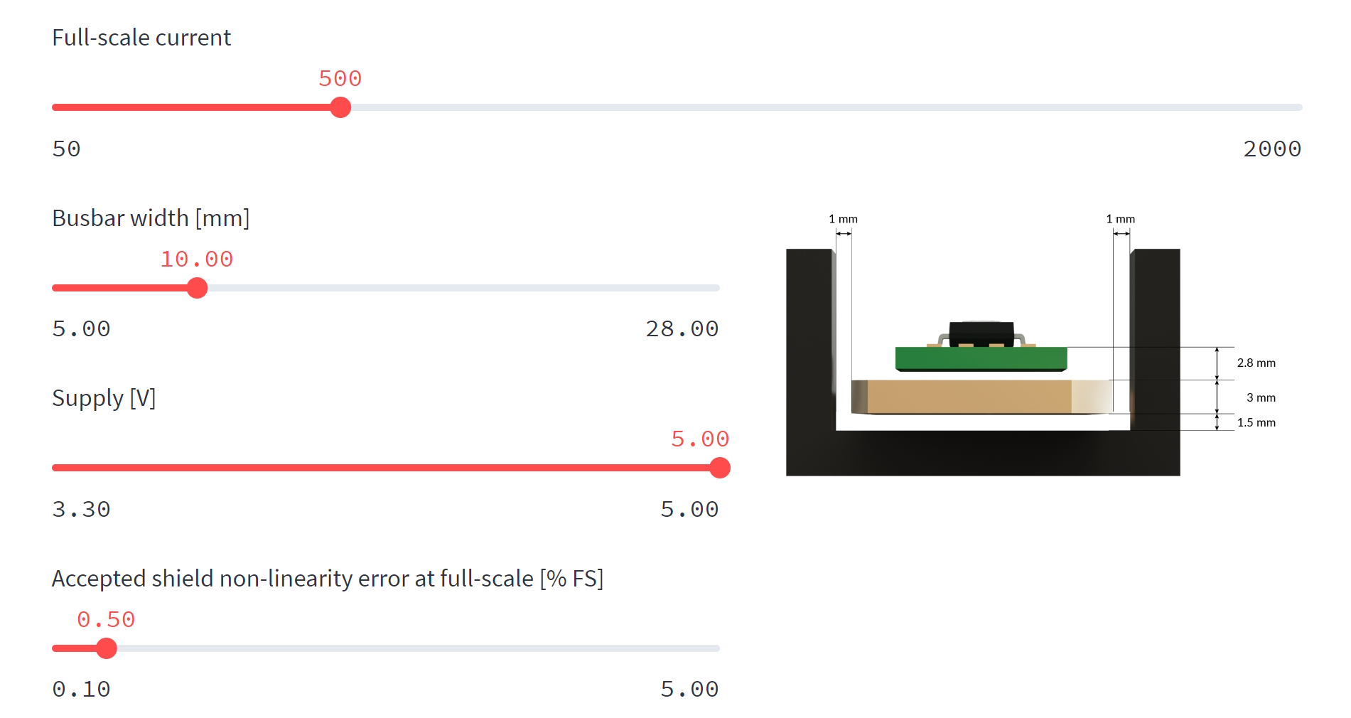
For designers of current sensing functions, Melexis offers its Current Sense Simulator. This web-based application speeds the selection of the company’s IMC-Hall sensors. Users fill in parameters on the screen to describe the design requirements, and the simulator recommends the appropriate part number and the corresponding ferromagnetic concentrator (shield). The simulator also calculates the total error budget across the full current sensing and operating temperature range. The default temperature range is -40 to 125 °C. For reduced temperature ranges, the error budget can be improved since sensor performance degrades at high temperatures. The simulator assumes certain mounting geometries and spacings. Designers input the full-scale current, busbar width, supply voltage, and accepted shield non-linearity error as a percentage of the full-scale measurement (Figure 1).
Designers of Internet of Things (IoT), industrial,l and medical applications using ±2g/±4g/±8g/±16g low power 12-bit digital accelerometers, ±2g/±4g/±8g low g 14-bit digital accelerometers, ultra-low power and low-voltage magnetic switches and/or digital motion sensors that combine a three-dimensional (3D) ±2g/±4g/±8g accelerometer and a 3D magnetometer can turn to the FreeMASTER Sensor Tool from NXP. The tool supports sensor evaluation, data visualization, and application development. It includes out-of-box sensor demonstration graphical user interfaces (GUIs) for quick sensor evaluation and a development framework for end users to create their custom applications. It supports JavaScript-powered HTML control forms where designers can choose from a collection of open-source instrumentation gauges, dials, knobs, and sliders to create custom user dashboards.
Photonic SoCs and sensors
Several companies offer general EDA tools to support sensor system designers. For example, Siemens’s sensor and IoT solution includes IC design, verification, manufacturing, and testing and supports advanced packaging, 3D IC, and PCB design and manufacturing. Tools in Siemens Xcelerator EDA portfolio support:
- Balancing hardware and software functionality in sensor and IoT system-on-chip (SoC) designs.
- Power estimation software to optimize low-power performance.
- Vendor-independent FPGA synthesis and optimization.
- Support for 3D IC designs for “More than Moore” application solutions.
- Embedded functions like design for test blocks and integrated analytics to maximize sensor and IoT SoC producibility and functionality.
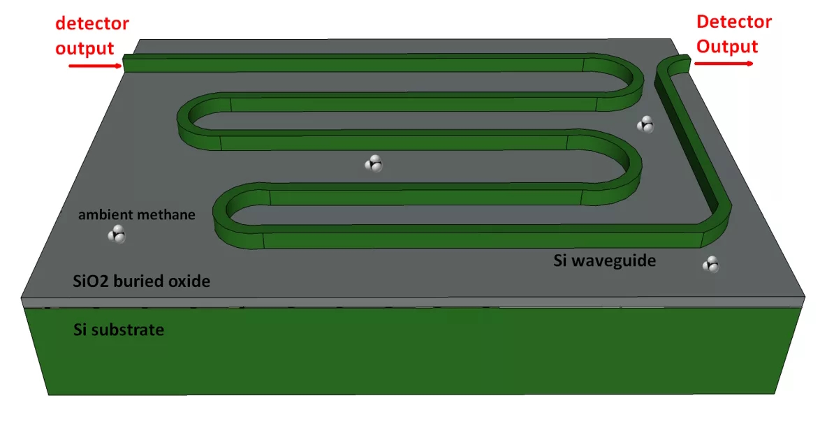
Synopsys’ OptSim supports the design of photonic and fiber optic sensors. OptSim provides accurate modeling of sensor physics, including optical phase, interferometry, and bidirectional signal propagation. Applications that can benefit from the OptSim development environment include interferometric fiber-optic gyroscope (iFoG) for aerospace and defense systems, automotive time-of-flight (ToF) and frequency-modulated continuous wave (FMCW) LiDAR systems, optical coherence tomography (OCT) for biomedical systems and industrial thermal and stress sensors and gas sensors (Figure 2). Key features include:
- Modeling nonlinearities, polarization dependencies, noise, crosstalk, and jitter.
- Libraries of photonic sensing elements include waveguides, fibers and fiber gratings, interferometers, ring filters, and others.
- User options include data visualization and plotting, design setup and project management tools, and Monte Carlo analysis.
Summary
Sensors provide critical links between the world and electronic systems. There’s a wide range of sensor technologies and an even wider range of sensor applications. Fortunately, there’s also a wide range of EDA tools available to designers to support rapid integration of sensors. Those tools are available from sources like component makers, general EDA tool makers, and specialist EDA tool suppliers.
References
FreeMASTER Sensor Tool, NXP
Magnetic sensing proximity tool, Texas Instruments
Online Current Sensor Simulator, Melexis
OptSim for Sensor Systems, Synopsys
Sensor & IoT design, Siemens