Temperature is the most frequently measured real-world variable, and despite its age, thermocouples are still among the most-used temperature sensors. They are used in test and measurement equipment, instrumentation, and even in standard home ovens due to their low cost, reliability, simplicity, and ability to measure into hundreds of degrees.
What is a thermocouple and how does it work?
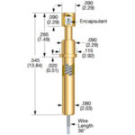
A thermocouple is a sensor comprised of two wires of dissimilar metals welded together at their ends, (Figure 1). The wire pairing generates a small voltage along its length in a repeatable relationship to the temperature, in accordance with a principle of physics called the Seebeck effect, after physicist Thomas Johann Seebeck, who discovered it in 1821 (he didn’t know what it was at the time; Hans Christian Ørsted realized it was actually a thermoelectric effect). The voltage is relatively small, ranging from a few millivolts negative to tens of mV, depending on sensed temperature and metals used.
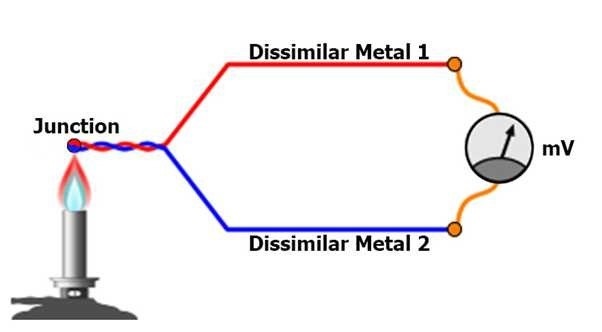
Contrary to common assumption, the voltage is not generated at the junction itself, although that misunderstanding does not affect using the thermocouple.
Why use a thermocouple to sense temperature?
- There are many reasons why the thermocouple is often used, despite the availability of many other temperature sensors such as solid-state devices:
- it’s low cost;
- it’s accurate and repeatable: a basic thermocouple can provide accuracy to 1 or 2°C, and with care and calibration, a performance of 0.1°C accuracy can be achieved;
- depending on metal pairings used, thermocouples can function in the hundreds and even thousands of degrees
- they are reliable: there is almost nothing to go wrong with the sensor except an open circuit failure (which is easily detected). A thermocouple cannot go out of calibration since its performance is a function of the composition of the two metals of the wires which form it, although it can be affected by corrosives or chemicals;
- performance is consistent, as thermocouples made from high-purity metals will behave according to a well-known temperature/voltage relationship;
- thermocouples can be configured and arranged to fit a wide variety of challenging physical situations and enclosures.
What are some of the drawbacks of thermocouples?
- the wires themselves can be expensive, such as when platinum or specialty allows are used;
- since the thermocouple is made of conducting metals, it must often be electrically but not thermally insulated from its surroundings;
- the response time-constant of the thermocouple is a function of its mass, so a larger or longer one may have a response time on the order of seconds, and tiny thermocouples are used to overcome this issue;
- since the output voltage of a thermocouple is small, the interface circuitry can be difficult to design and implement;
- the output of the thermocouple is not linear and must be corrected, in most cases (more on this in Part 2);
- the interconnection between the two wires of the thermocouple and the regular copper-wire cable or connector forms yet another thermocouple, for which compensation is needed (more on this is Part 2);
- depending on how they are mounted and protected, their wires can be subject to bending, fatigue failure, and an eventual open circuit (again this is easy to detect electrically).
What are the most commonly used thermocouple-wire types?
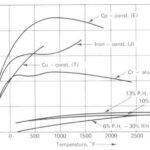
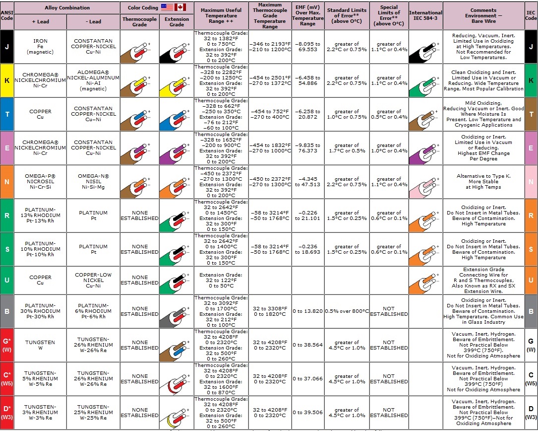
The industry has adopted and characterized many types (Figure 2), such as Type J, Type K, and others. Each is standardized in terms of material pairings, performance, insulation color, and other attributes. Users select the best pairing based on range, accuracy, and acceptable or preferred operating environment.
What is the relationship between temperature, thermocouple type, and Seebeck voltage?
The relationship is monotonic, nonlinear, a function of the metals in the pair, and the purity of the metal used is a factor, too, of course. While many tables were developed in the early days of thermometry, their importance to industry and science led the ASTM (previously known as the American Society for Testing of Materials) and Department of Commerce’s National Bureau of Standards (NBS) – now the National Institute of Standards and Technology (NIST) – to develop detailed, highly accurate, standardized tables showing the temperature-voltage input/output relationships in both directions.
They also did complex curve-fitting to develop sophisticated non-linear equations which can be used in place of the tables to calculate the temperature from a voltage and vice versa, for all standard types.
Can thermocouples be used for anything in addition to measuring temperature?
Absolutely, yes: they are used as heat-powered voltage/power sources in down-to-Earth products as well as some applications that are literally out of this world. For example:
- Many gas-fired home water heaters have a small pilot light to ignite the burner when the water must be heated. For safety, there is a valve interlock that opens and allows gas flow only if the burner comes on (to prevent dangerous the ongoing flow of gas that is not being combusted, an obvious danger. The power for the valve activation comes from an array of thermocouples around the burner, such that some of the burner flames heat the thermocouples, which in turn generates the voltage needed to activate the relay and keep the valve open. It’s a low-cost, highly reliable, simple, fail-safe design;
- Some camping stoves, such as ones from Biolite, use thermocouples in the stove’s flame to power a small fan and so improve airflow and combustion; some models even use this power to provide a USB charging port. Of course, there is no “free lunch”: any heat absorbed by the thermocouples for the fan or charger function is heat that is not available for cooking;
- Finally, all spacecraft that travel beyond the inner part of our solar system use thermocouple-based sources for power, since the Sun’s rays are too weak to be effective with solar panels. The radioisotope thermoelectric generator (RTG) is a canister of radioactive material, usually plutonium-238, surrounded by hundreds of thermocouples.
As the plutonium undergoes its natural radioactive decay, that heat is captured by the thermocouple array to generate constant power, with up to several hundred watts a practical maximum. Since the half-life of plutonium-238 is 70 years, this “battery” can be viable for decades. This has been proven by the Voyager 1 and Voyager 2 spacecraft which were launched in 1977 and have gone beyond the edge of our solar system and are still transmitting.
Thousands of these RTGs have been used for deep-space missions, for long-life missions closer to Earth, landers on the dark side of the moon, and even to power science and beacon stations near the Earth’s North and South poles.
Part 2 of this FAQ will look at thermocouple interface issues, cold junction compensation, and linearization techniques.
References
There are thousands of quality references on all aspects of thermocouples, from basic theory to application and more; among them are:
- https://www.dewesoft.com/pro/course/temperature-measurement-2.
- https://www.sterlingsensors.co.uk/thermocouples