Part 1 of this FAQ looked at the basics of thermocouples, where and why they are used, and some basic implementation issues; this part explores interface issues, cold junction compensation, and linearization.
What are the requirements for thermocouple interface electronics?
The thermocouple voltage is relatively small, so long leads between the thermocouple and the electronic front-end circuitry are liable to pick up noise that corrupts the signal. This interface circuitry must take the small voltage and linearly amplify it at a fixed, constant gain regardless of signal level to a higher voltage, usually up to 5 to 10 V at maximum. The amplified signal can be used directly to drive a readout, or digitized and then used by software for readout or for use as a feedback signal in a closed-loop control system.
Can thermocouples be multiplexed?
Many test installations have dozens or hundreds of thermocouples to measure temperature at many points in the system. Using a separate, complete front end for each might be prohibitive in size, cost, or power dissipation.
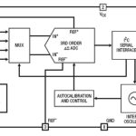
Instead, a system- or user-controlled multiplexer (mux) can be used so that a single front end can service all the thermocouples. This is not necessarily a simple design, as any differences in performance due to the switches in the multiplexing circuitry may induce small errors in the readings. This would appear as inconsistencies and offsets between channels, making correlations misleading. Still, the many costs of using fully independent front ends for each of the many thermocouples means that a properly designed multiplexed approach may be the best choice.
What is cold junction compensation and why is it needed?
As noted in Part 1, a Seebeck-effect thermocouple occurs whenever two dissimilar metals are in contact. In fact, it occurs in unexpected junctions such as when a copper wire in connected via a terminal, connector, or screw which is plated with another metal, such as nickel, to avoid corrosion; a solder-copper connection can also have the same effect. The effects of this unintentional thermocouple must be factored into high-accuracy temperature-related instrumentation.
Therefore, the unavoidable connection between the thermocouple wires and the associated contacts and wiring becomes another thermocouple and affects the reading. To correct for this, a local temperature sensor is used at the connection panel or point, and this is referred to as the cold junction. This cold-junction temperature reading is then used to correct for the effect of the inadvertent thermocouple created at the connection point, and the entire function is called cold junction compensation (CJC). Note that the CJC temperature reading does not need high accuracy in most applications, as it is a second-order error; therefore, many CJC installations can use a low-cost, limited-range, modest-accuracy (2°C) solid-state sensor or thermistor to provide the CJC reading.
How can the nonlinearity of a thermocouple be corrected?
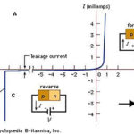
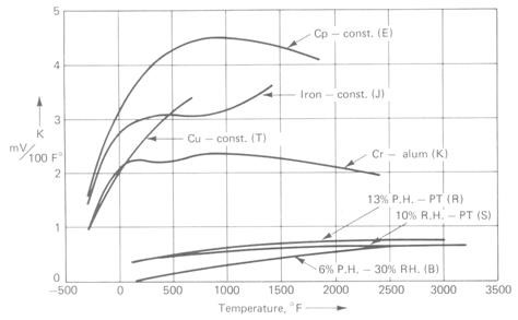
Thermocouples have a consistent, repeatable nonlinearity in their temperature/voltage relationship, (Figure 1). There are three ways this can be done, in cases where the nonlinearities would result in an unacceptably large error. (Note that there are many applications where an error of even four or five degrees is not an issue.)
The options are:
- Prior to the availability of low-cost, high-performance processors, the most common way to linearize the thermocouple reading was with all-analog circuitry. Here, the piecewise-linear approximation of a thermocouple output — again, as detailed by the NBS/NIST — was the basis for the design. The analog circuitry was designed to implement slightly different gain values along the entire range, with the gain changing at pre-defined breakpoints. This worked but required careful circuit design to make sure the breakpoints themselves stayed at their designated values despite component tolerance and aging, and changes in ambient temperature Due to its cost, complexity, and lengthy bill of materials, this method is rarely used now.
- Via a lookup table, with the details of the standard NIST table placed into a table in system memory. Each voltage output from the thermocouple is used as the input variable for the table, and the table provides a corresponding temperature reading as its output (some applications used a reverse temperature-to-voltage table, of course). This method requires a relatively large amount of memory (expensive in the early days, very cheap now) and is fast, as it only requires front-end signal conditioning/amplification and then a single look-up step. Note that the entire NIST table is usually not needed, but only the part that is relevant to the thermocouple’s range of operation in the application.
- For cases where memory is limited, calculations and processing time can be used instead. Here, the input signal is used with the appropriate NIST polynomial equation (Figure 2), and coefficients for that thermocouple type, and then the corrected value is calculated.
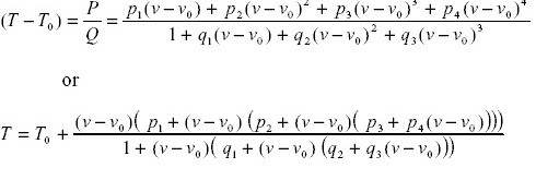
This is effective but requires many processing cycles as well as the use of floating-point math (or fixed-point math which emulates floating point) to ensure that roundoff and truncation errors do not accrue and cause unacceptable errors in the resultant “linearized” value. Again, only the coefficients for the range of operation are needed.
Despite the availability of many alternatives for temperature measurements, including solid-state sensors, infrared sensing, and material expansion/contraction, the thermocouple remains a very popular, widely used sensor due to its low cost, repeatability, ruggedness, reliability, and ability to function at high and low-temperature extremes.
References
- NIST Publication 250-35, “The Calibration of Thermocouples and Thermocouple Materials”
- “Conversion of Thermocouple Voltage to Temperature”
- Texas Instruments TIDUA11A, “Optimized Sensor Linearization for Thermocouples”