• Skip to primary navigation
  • Skip to main content
  • Skip to primary sidebar
  • Skip to footer

Analog IC Tips

Analog IC Design, Products, Tools Layout

  • Products
    • Amplifiers
    • Clocks & Timing
    • Data Converters
    • EMI/RFI
    • Interface & Isolation
    • MEMS & Sensors
  • Applications
    • Audio
    • Automotive/Transportation
    • Industrial
    • IoT
    • Medical
    • Telecommunications
    • Wireless
  • Learn
    • eBooks / Tech Tips
    • FAQs
    • EE Learning Center
    • EE Training Days
    • Tech Toolboxes
    • Webinars & Digital Events
  • Resources
    • Design Guide Library
    • Digital Issues
    • Engineering Diversity & Inclusion
    • LEAP Awards
    • Podcasts
    • White Papers
  • Video
    • EE Videos
    • Teardown Videos
  • EE Forums
    • EDABoard.com
    • Electro-Tech-Online.com
  • Engineering Training Days
  • Advertise
  • Subscribe

RTD vs. thermocouple vs. thermistor in temperature sensors

December 29, 2016 By Janet Heath Leave a Comment

Temperature doesn’t change very quickly, and temperature sensors match that characteristic. Environmental temperature changes are generally slow, on the order of less than 0.1 sec/°C. Typical circuit temperature sensors are resistance temperature devices (RTDs), thermocouples, thermistors, or integrated silicon sensors. Trade-offs amongst these devices include cost, cost to operate, response time, noise immunity, operating temperature range, and stability. Stable devices will produce less output signal drift over time, which reduces the need for repeat calibrations.

Table 1: Comparison of temperature sensing technologies. Adapted from A Baker’s Dozen: Real Analog Solutions for Digital Designers, by Bonnie Baker.

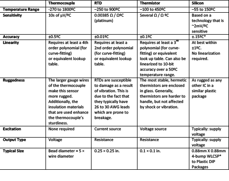
Thermocouples are inexpensive, rugged, stable, operate over a wide temperature range, and are relatively linear over a wide range but deviate significantly at extremely cold or hot temperatures. They have two different types of conducting wires that form electrical junctions at two different temperatures—one junction is at a reference temperature, and the other junction is at the temperature being measured.

A thermocouple generates a voltage that correlates to temperature, a result of the Seebeck effect. To generate a linear signal, thermocouples require a controller with a look-up table of thermoelectric voltages and coefficients. Standard types of thermocouples have known curves, and curve-fitting coefficients are available from the National Institute of Standards and Technology (NIST).

Figure 1. This thermocouple probe’s head is filled with an epoxy that encapsulates the thermocouple and insulates it from electrical interference. (Source: Interconnect Devices, Inc.

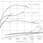
RTD elements change resistance values with temperature changes. RTDs are wire-wound for high-temperature applications and can be fragile. RTDs for low-temperature applications are thin-film (flat-film) serpentine elements mounted in a substrate. They are offered in several metals, including platinum, copper, nickel, and nickel-iron. The platinum RTD is the most accurate sensor of all types of sensors covered in this article. It covers a broad temperature range, is stable, demonstrates good noise immunity, and has excellent repeatability and linearity, yet it is the most expensive option.

However, a stable reference current must be provided to measure the resistance­ value of the RTD element. RTDs require a look-up table or equation to interpret temperature values in relation to the output.

Thermistors are temperature-sensitive resistors known for their rapid response. Like RTDs, thermistors change in resistance with changes in temperature and require excitation. However, the elements are made of ceramic or polymer instead of metal. Thermistors generally have higher resistance values versus RTDs and, therefore, operate with lower reference currents and, thus, lower energy consumption.

With different materials, thermistors can achieve greater precision, albeit over a limited temperature range. Thermistors require a look-up table or equation to interpret temperature values in relation to the output. Thermistors are also used for circuit protection as current limiters and as heating elements.

Figure 2: Plot of resistance versus temperature for RTD and various Thermocouples. (Source: Texas Instruments)

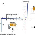
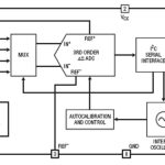
Semiconductor temperature sensors are based on the temperature-dependent relationship between the base-emitter voltage and the collector current of a bipolar junction transistor (BJT). Semiconductor-based temperature sensors are easily integrated within semiconductor ICs but are slow to respond to fast temperature changes. The size of semiconductor sensors has decreased such that they are a competitive choice to RTDs for some applications.

References

[i] Kuglestadt, Thomas. Semiconductor Temperature Sensors Challenge Precision RTDs and Thermistors in Building Automation. Apr. 2015. Dallas, Texas.

[ii] Bonnie Baker, A Baker’s Dozen: real analog solutions for digital designers (Amsterdam: Elsevier/Newes, 2005).

You may also like:


  • Solid-state temperature sensing, part 1: principles

  • Making sense of thermocouples and interfaces: part 2

  • Making sense of thermocouples and interfaces: part 1
  • thermocouple-image-2
    Using and interfacing to thermocouples

Filed Under: FAQ, Featured, Industry Experts, MEMS & Sensors, Products Tagged With: basics, FAQ

Reader Interactions

Leave a Reply Cancel reply

You must be logged in to post a comment.

Primary Sidebar

Featured Contributions

Design a circuit for ultra-low power sensor applications

Active baluns bridge the microwave and digital worlds

Managing design complexity and global collaboration with IP-centric design

PCB design best practices for ECAD/MCAD collaboration

Open RAN networks pass the time

More Featured Contributions

EE TECH TOOLBOX

“ee
Tech Toolbox: Power Efficiency
Discover proven strategies for power conversion, wide bandgap devices, and motor control — balancing performance, cost, and sustainability across industrial, automotive, and IoT systems.

EE LEARNING CENTER

EE Learning Center
“analog
EXPAND YOUR KNOWLEDGE AND STAY CONNECTED
Get the latest info on technologies, tools and strategies for EE professionals.

EE ENGINEERING TRAINING DAYS

engineering

RSS Current EDABoard.com discussions

  • Persistent Shoot-Through vin=vout in Synchronous Buck Converter – Physical Phenomenon Issue
  • reccomendation for higher value Vout logic component for ttl
  • Power Management Dilemma for Pet Feeder
  • PCB layout impact on RF path impedance
  • Op-Amp oscillating

RSS Current Electro-Tech-Online.com Discussions

  • Converting 1vac to 24vac
  • AC Input Relay Device Required
  • WTB: "The Theory Of Servicing AM, FM, And FM Receivers" by Clarence R. Green and Robert M. Bourque
  • MLT-8530 Buzzer on ESP32: Why Is the Sound Output Lower Than Expected?
  • Scope Clock CRT Z-Axis - Grid bias positive?
“bills

Footer

Analog IC Tips

EE WORLD ONLINE NETWORK

  • 5G Technology World
  • EE World Online
  • Engineers Garage
  • Battery Power Tips
  • Connector Tips
  • EDA Board Forums
  • Electro Tech Online Forums
  • EV Engineering
  • Microcontroller Tips
  • Power Electronic Tips
  • Sensor Tips
  • Test and Measurement Tips

ANALOG IC TIPS

  • Subscribe to our newsletter
  • Advertise with us
  • Contact us
  • About us

Copyright © 2025 · WTWH Media LLC and its licensors. All rights reserved.
The material on this site may not be reproduced, distributed, transmitted, cached or otherwise used, except with the prior written permission of WTWH Media.

Privacy Policy