
Part 1 of this FAQ look at the coaxial cables used in microwave/millimeter wave interconnects and cable assemblies. But a cable alone is only half a solution; the cable must be terminated with connectors. Often, the completed cable/interconnect assembly is also called a cable, but this is generally not an ambiguous situation (but it may be in some cases, so be aware).
Q: What kinds of connectors are available for coaxial cables?
A: Dozens of standard connector types are available, matched to the corresponding cable size, frequency, and power-handling rating.
Q: Can you add these connector terminations yourself?
A: Yes and no. For the larger connectors (discussed below), it is possible to do it. While special tooling is helpful, it is not absolutely needed if the person doing it follows the instructions carefully and has some practice and skill. Some connectors require soldering, some use crimping, and some have just a mechanically tightened nut.
But, these do-it-yourself possibilities only apply to larger connectors and cables. Many of the newest cables and their connectors are extremely thin (just a few mm in diameter), the connectors are precision and fragile, and any imperfections in the assembly will severely degrade the electrical and mechanical performance. For these reasons, most of the cables and connectors used for the higher frequencies are ordered pre-made from a vendor who has the right equipment, tooling, and know-how to terminate the cable with the specified connector.
Q: What are the standard connectors?
A: There is no “standard,” but several are in widespread use due to their legacy status and longevity: the BNC, SMA, and PL-259.
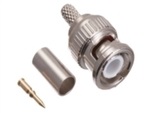
- The BNC connector (short for Bayonet Neill–Concelman, the latter two developed it in the early 1950s) is a bayonet connector for up to about 4 GHz, with a diameter of about 14 mm); it is available in both 50 and 75-ohm versions, Figure 1 (the two versions sometimes get mixed up and system performance suffers);
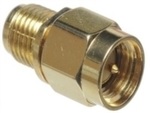
Figure 1: The classic BNC connector is still widely used, as it works up to about 4 GHz and is easy to attach/remove due to its “bayonet” locking; it can be terminated in the field with a modest amount of practice. (Image: Amateur Radio Supply) - the SMA (SubMiniature version A) screws on and is useful to about 18 GHz (sometimes versions can be used at higher frequencies); it is a 50-ohm unit with a diameter of about 8 mm, Figure 2;
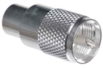
- the PL-259 (developed in the 1930s) has 18-mm diameter, also screws on and is useful to about 100 MHz, Figure 3;
- the 75-ohm F-type connector is used with cable TV and related systems and available in push-on and screw-on versions; it provides acceptable performance at low cost and can be terminated in the field.
But times have moved on and frequencies of interest have moved higher and higher, and these connectors are both too large for many of today’s applications and do not have the bandwidth needed for tens of GHz and higher operation.
Q: What other connectors are in widespread use?
A: There are many, some of which are optimized for a given application where one parameter (cost, loss, size) is much more important than others. A good listing with photos is available at the L-com site, under the listing “Coaxial Connectors.”
Q: What about connector versus frequency?
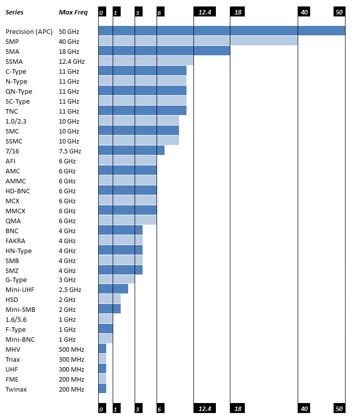
A: Again, there are many to choose from, due to the huge variety of application needs and priorities. Figure 4 shows many of them versus maximum useful frequency, but keep in mind that frequency is not the only specification; cost, size, power handling, and other factors are also part of the connector decision.
Q: How many connect/disconnect cycles can a connector pair tolerate?
A: It depends on how much performance degradation in various specifications is acceptable, among other factors A typical connector pairing is good for 50 to several hundred cycles, but it depends on the connector plating, the operating environment, and other factors. Two connectors can have identical electrical specifications but very different plating types and thicknesses, such as silver over nickel, and so differ dramatically in cycle performance.
Q: How are the mating connector halves designated?
A: It depends. In some cases, the same connector name is used, along with the modifier “male” or “female” where the male connector has a protruding pin corresponding to the coaxial cable center wire, while the female has a receptacle to accept the pin or contact. In other cases, the “male” and “female” halves have entirely different designations, such as PL-259 (male plug) and SO-239 (corresponding female socket). The reason for these different naming conventions are historical and related to the context in which the connector pair was developed and used.
Q: Does the cable get the male or female connector?
A: Usually, but not always, the cable gets the male connector while the chassis, panel, or next connection gets the female. But there are exceptions, and connectors are available for all situations.
Q: What if I need to connect one type of connector with another type, due to a design issue, mismatch, or emergency?
A: The good news is that adapters are available for almost every situation and mismatch combination. For example, you easily can get a BNC-to-SMA adapter. However, these adapters must be used with caution, as an interconnect is only as good in overall performance as its weakest link.
There are also “reverse polarity” connectors which have a male body and female center contact, or vice versa. These can be real problem-solvers in unusual situations, so the entire cable assembly does not have to be replaced or remade.
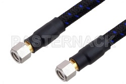
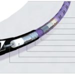
Q: What’s an example of a standard, available cable assembly for higher frequencies and high performance?
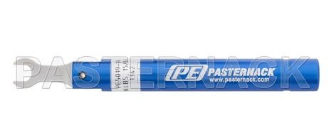
A: Several vendors offer 110-GHz cable assemblies needed for advanced test scenarios, Figure 5. These cables are only one mm in diameter, and the connectors are correspondingly tiny. Any imperfection in the connector, or its termination to the cable, or even dust specks, will adversely affect performance, so they must be visually inspected before each use. One vendor even offers a specialized “break-over” torque wrench pre-set to 4 in-lbs (0.45 N-m maximum), Figure 6, to ensure the connector is torqued “just right”—it’s that critical.
References
Microwaves 101, “Why Fifty Ohms”
Belden, Inc., “50 Ohms: The Forgotten Impedance”
W.L. Gore, “Gore Phaseflex”
L-Com, “Coaxial Cable Tutorial”

