Analog circuits are exposed to outside influences most often through input channels by way of op amps acting as filters, buffers, or amplifiers. Electrostatic discharge (ESD) results from the direct contact of two things that are at different voltage potential levels and can also be defined as a fast, high current transfer. Analog circuit exposure to ESD can occur through any connection with the outside world through sensor input connections, for instance, as well as the usual routes of mishandling. A person walking across a carpet can generate around 1kV, whereas walking across a vinyl linoleum floor can generate 150 to 250v. Handling an IC without grounding oneself first can cause considerable damage, if not catastrophic damage to the circuit. And yes, you are actually applying those levels of voltage to the integrated chip when you walk across a carpet and it pick up. Yes, there are internal protections integrated into most ICs, but the human body model shows that 5.5kV and greater are possible as well. Does your datasheet indicate 5.5kV as the maximum?
Selecting a random general purpose op amp from the Texas Instruments line up (TLV170 released in 2016), shows an ESD absolute maximum rating of +/- 4kV. That’s pretty good. But did you know that each zap of ESD can be an additive damage? Junction damage may increase with each exposure until it finally fails. An ESD zap of around 6kV will be perceived by most as painful.
Damage to an IC in this way results in impaired specifications or an increased degradation over time. The quality of the IC could be impaired such that although the chip works, it does not exhibit the quality that it had when it was tested in the fab and can degrade with use. The insidious issue with ESD is that once it occurs, there are no visible signs that the chip was exposed to overvoltage. Thus, it is imperative that manufacturers, distributors, and PCB makers take protection seriously as well as the hobbyist who receives a chip in the mail and solders it into his or her project design themselves.
Unpowered ICs are still vulnerable to extreme overvoltage applied to supply voltage pins. (All pins provide an open path for the effects of overvoltage caused by ESD, however.) Internal circuits on an IC are typically protected by integrated components such as diodes within the IC, so ICs are not completely unprotected (in general; your mileage may vary.) However, if an ESD zaps the IC with a greater potential than the drop across the diode can block, for instance, current will flow through the circuit in the chip as the ESD-induced voltage potential seeks a path to a lower potential point in the circuit. Let’s assume that the input circuit experiences the energy potential supplied by ESD, not the power supply rail. The input circuit could end up experiencing a powered state, as well as anything else that touches the supply voltage rail inside the IC that the input circuit is connected to.
Rules of thumb
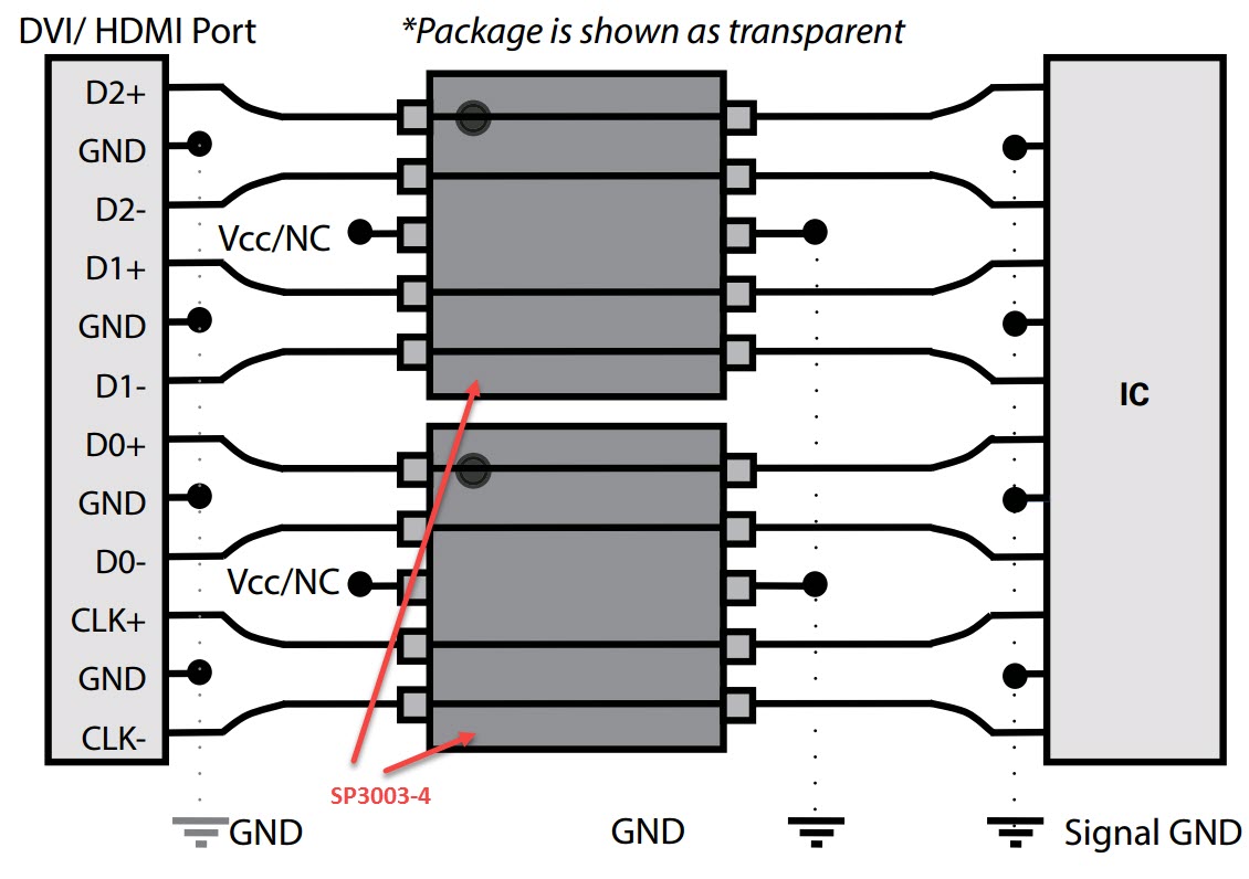
Always strap yourself in with a wrist band and handle chips carefully. You cannot live life strapped to a wrist band, however, so other precautions can be taken. A low humidity environment (winter) is more prone to build-up of ESD charges, as is a carpeted environment for those handling ICs. Your workshop should be vinyl or other hard flooring. Use a humidifier if you live in a cold environment, since voltages can increase by ten times in cold weather in indoor environments (i.e., relative humidity of about 30%RH or lower, versus warm weather conditions of around 60%RH.) Ground yourself before handling devices or PCBs if you don’t have a wrist strap. Hold PCBs by the edges with little to no contact with traces. Connectors and data connection points are known entry points for ESD in everyday handling of electronics, so commercial electronic devices are going to have sufficient ESD protection at USB ports, for example, as long as the electronic device was manufactured by a reputable entity.
In general, a 5mA current is safe for op amps, but charges that induce a reverse bias junction breakdown are damaging at any current level. You can apply large-value external series resistance (BiFET-type op amps) and external Schottky diodes as overvoltage clamps (bipolar op amps) for input analog circuit protection. (Op amps are very often the first stage in the input circuit from the outside world.) Circuit protection guides are available for using standard discrete components from many manufacturers that show how to implement discrete components with circuit diagrams. The Littelfuse site has circuit diagrams for many application designs listed under their Technical Resources section. Drilling down through the applications reveals specific protection devices that are recommended for each application as well as schematics on how to apply the protection devices.
Adding discrete external components can change the expected analog performance, however. For precision analog circuit devices with higher voltage and peak current, external components are especially relevant because the usual protection devices on input stages also increases input current leakage. Diodes provide a path for leakage current in normal operation. A series resistor acts to increase settling time. Discrete components are fine if precise and linear measurements are not required.
However, there are alternatives to traditional ESD protection with external components but finding them might require more research.
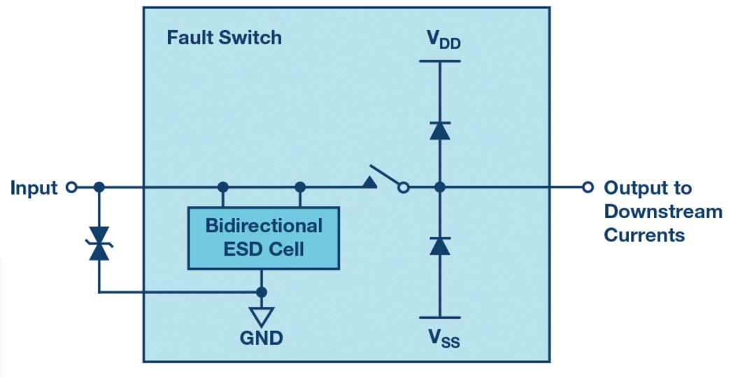
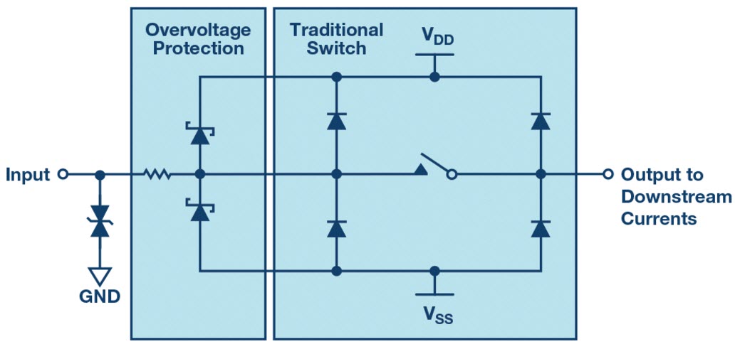
Analog Devices has a fairly new portfolio of fault protected analog switches and multiplexors that can be used with precision measurement and instrumentation applications. As an alternative to discrete components, settling time and linearity are impacted less with the Analog Devices solution than when using discrete components. For most designs, the Analog Design offering might be overkill, but it’s good to know that alternatives exist when board space and performance are critical. This is just one example of products that are out there that can be used in place of discretes. For more information on the ADI solution, see “Replacing Discrete Protection Components with Overvoltage Fault Protected Analog Switches s” by Paul O’Sullivan on the analog.com website.
The overall point here is to not take internal IC protection for granted when handling ICs. If you cannot guarantee safe handling, additional external protection may be necessary. An ounce of prevention is worth a pound of troubleshooting, especially when it comes to the complexities of analog circuits handling real-world signals.
Leave a Reply
You must be logged in to post a comment.