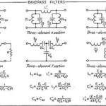
The well-known and extensively analyzed lumped-element bandpass filter is generally not suitable for the RF/microwave region, but there are many distributed-element, energy-based alternatives.
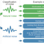
Just say the word “filters,” and for many engineers, the mention of this topic stirs a mix of feelings ranging from fear to relief. Why fear? Because filters as a topic in school were, to put it politely, “challenging” with intense math, Bode plots, poles and zeroes, weird-sounding topologies such as pi, Chebyshev (one of several spellings), Sallen-Key, Butterworth, and biquad, along with unique parameters and metrics such as in-band ripple, skirt rolloff, insertion loss, and more. Yet, at the same time, they also bring relief as a filter is often a design-saving necessity. A properly designed or chosen filter generally essential to a system and circuits proper operation. Among other roles, it squelches unwanted signals while advancing desired ones, enhances signal/noise ratio (SNR), and gets rid of noise and interference, and more.
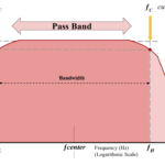
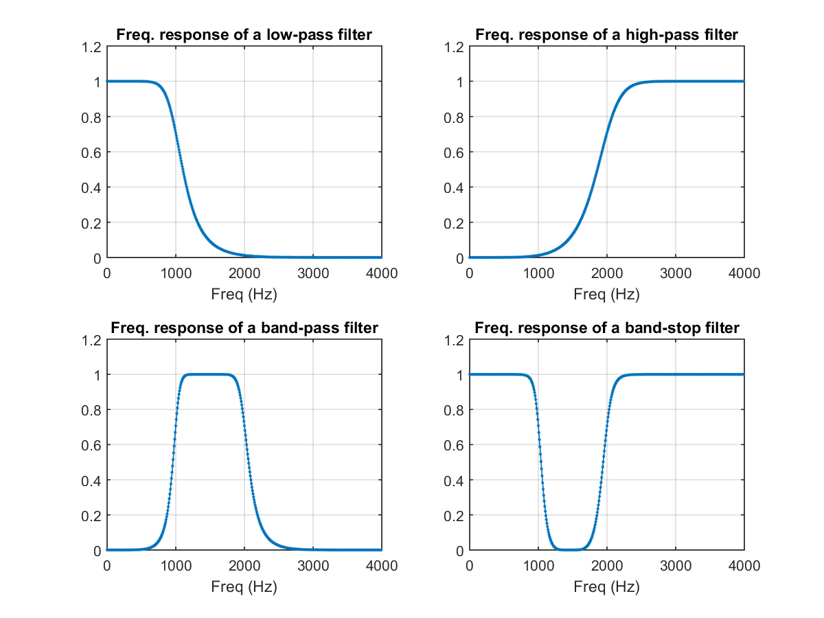
Filters come in basic classes: low-pass filters (LPF), high-pass filters (HPF), and bandpass filters (BPF, and the notch filter (the inverse of the bandpass filter) (Figure 1). Each has a critical role in the overall system, but in many ways, bandpass filters now have the most changing demands placed on them. They must allow a (usually) narrow desired signal to pass, while severely attenuating the undesired energy on both sides of that signal. In contrast, low- and high-pass filters typically have a broader role such attenuation of energy above or below a given frequency, respectively. There is less need for sharpness in the cutoff frequency compared to bandpass filters, which must very selectively pass just a thin sliver of the spectrum with minimal distortion and corruption.
Goodbye, lumped-element filters
While the basics of filter theory are by no means unneeded, the conventional filter analysis and realization based on lumped, discrete electronic components is now a much smaller part of the filter menu. Therefore, a large part of RF/microwave work involves a different approach to filters rather than a look at voltage versus frequency along with how to use resistors, inductors, and capacitors (RLC) components in passive or active filters.
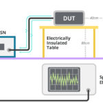
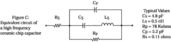
Why is this so? As frequencies reach into the hundreds of megahertz and then into tens of gigahertz, the RF reality of lumped-element filters becomes a major limitation. While the RLC (mostly LC) components values and physical sizes are quite small, the unavoidable associated internal and external parasitics become significant relative to the component values, these parasitics are difficult to model accurately, and it is nearly impossible to maintain performance consistency especially in a production setting (Figure 2).
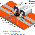
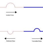
Instead of lumped/ discrete elements comprising a filter, filters for these higher frequencies use single or multiple resonances of electromagnetic energy and power in place of voltage relationships. Management of this energy at the different frequencies is how the filter provides its functionality.
What do we look for in RF/microwave filter performance? The standard lumped-element parameters apply, such as center frequency, 3-dB bandwidth, attenuation within and outside of the passband, selectively, rolloff, and passband/stopband ripple, to cite just a few.
Hello, distributed filters
However, how you try to implement these RF/microwave filters to achieve the desired performance specifications changes. In contrast to attempting to design and then implement a lower-frequency discrete-element filter, very few designers will create and then try to realize the RF/microwave filter – it’s simply not practical. Instead, they look to get a single component that can provide the entire bandpass-filtering function.
This BPF component appears on the bill of materials (BOM) as a single purchased line item. It is a “sealed box” having few or no adjustments. Some broad spectrum of RF energy goes into it, and out of it, some bandpass-limited amount of RF energy emerges. This filter is characterized by its operating on signal energy and power rather than voltage and current, although power and energy are related to voltage and current. Other attributes which designers look at when choosing (and not designing) these single-component filters include but are not limited to Insertion loss, size, power-handling capacity, Q, VSWR, roll-off rate, ripple, peaking, and cost (of course).
Recall that Q or quality factor is a unit-less measure of selectivity computed as the ratio of the filter frequency to bandwidth and can range anywhere from double digits to high triple digits. Depending on the application, higher or lower values of Q are needed: bandpass filtering of a single 1-MHz channel from the 2.4 GHz Wi-Fi spectrum needs a high-Q filter. In comparison, bandpass filtering of an entire 2.4 GHz Wi-Fi band (nominally 2.4 to 2.5 GHz) from the spectrum around it mandates a lower-Q BPF. In general, a higher-Q device is better and preferred (but not always) and costs more than a lower-Q device.
These filters are most often built not from discrete RLCs (even tiny ones) but instead employ electromagnetic-energy principles, modern twists on well-known materials, new engineered materials, and sophisticated fabrication technologies. These result in high-performance, small BPFs with consistent and predictable specifications from unit-to-unit and across temperature.
As with any component, filter design and execution requires tradeoffs and compromises in the context of the relative priorities of the application. These filters can also be designed to provide impedance matching between source and load when aided by the use of the Smith Chart.
Part 2 of this article will look at some widely used RF/microwave filter options in terms of their architecture and fabrication, not electromagnetic filter-theory details. It is not intended as a design guide, and there will be no math, but there will be some small allusions to electromagnetic principles and physics. Also, this article will not discuss the also popular acoustic-wave resonant filters such as surface acoustic wave (SAW) and bulk acoustic wave (BAW) devices, as these have been covered previously (see Reference).
EE World References
- Basics of bandpass filters
- What are the functions and principles of S-parameters (Part 1)?
- What are the applications and measurements of S-parameters? (Part 2)
- Using the Smith chart for Impedance matching, Part 1
- Impedance matching and the Smith Chart, Part 2
- Printed Circuit Boards, Part 1: Context and phenolic boards
- The basics of FR-4 Printed Circuit Boards
- Printed Circuit Boards, Part 3: Vias and multilayer boards
- Printed Circuit Boards, Part 4: Beyond FR-4
- Filters, Part 2: SAW and BAW devices for RF
External References
- Knowles Capacitors, “Microstrip Filters Deliver Small Size at High Frequencies”
- Skyworks Solutions, Inc., “Glossary of Terms for Coaxial Resonators and Coaxial Inductors”
- Skyworks Solutions, Inc., “Measuring SRF and Q of Coaxial Resonators”
- Skyworks Solutions, Inc., “Characteristic Impedance of Coaxial Resonators”
- Johanson Technology, “SRF & PRF for RF Capacitors”