There is a device that squashes all the 1/f voltage and current noise calculations with a chopper amplifier algorithm that corrects offset and drift characteristics. These amplifiers are zero-drift, auto-zero, or choppers that all achieve nanovolt-level offsets and extremely low offset drifts due to time and temperature. But back to our noise discussion, these devices reshape amplifier noise density in a very positive way.
Let’s dig back into the 1/f noise operational amplifier phenomena for a final time. This discussion will look into DC-coupled measurements, such as thermocouples, thermopiles, precision DAC output amplifier, or current shunt sensors, which commonly require a high DC gain, precision amplifier. The gain term of amplifiers in the DC measurement application space as high is as 1,000 Volts/Volts (V/V) or larger. The microvolt (μV) to millivolt (mV) 1/f noise error recks havoc with this amplifier gain stage by showing a large output voltage offset in a high closed-loop gain circuit. For example, an amplifier’s 5 μV p-p 1/f noise in an amplifier gain of 5,000 V/V produces a 2.5 mV output error.
The auto-zero, zero-drift, or chopping amplifier brings the 1/f error to a minimum with high-frequency analog signal processing. Technically these amplifiers utilize all these design strategies to create an amplifier with 1/f noise that appears as a slowly varying or nearly constant input voltage offset.
Figure 1’s auto-zeroing amplifier corrects any DC or low-frequency offsets, which includes 1/f noise.

In Figure 1, an auto-zero amplifier corrects the input offset with Phase A and Phase B in two clock phases. The switching frequency between these two phases is beyond the amplifier bandwidth.
The topology combination of auto-zero and chopping brings exceptionally low offset, offset drift, and noise to system applications. This topology reduces the characteristic1/f curve to obscenely constant, low levels (Figure 2).
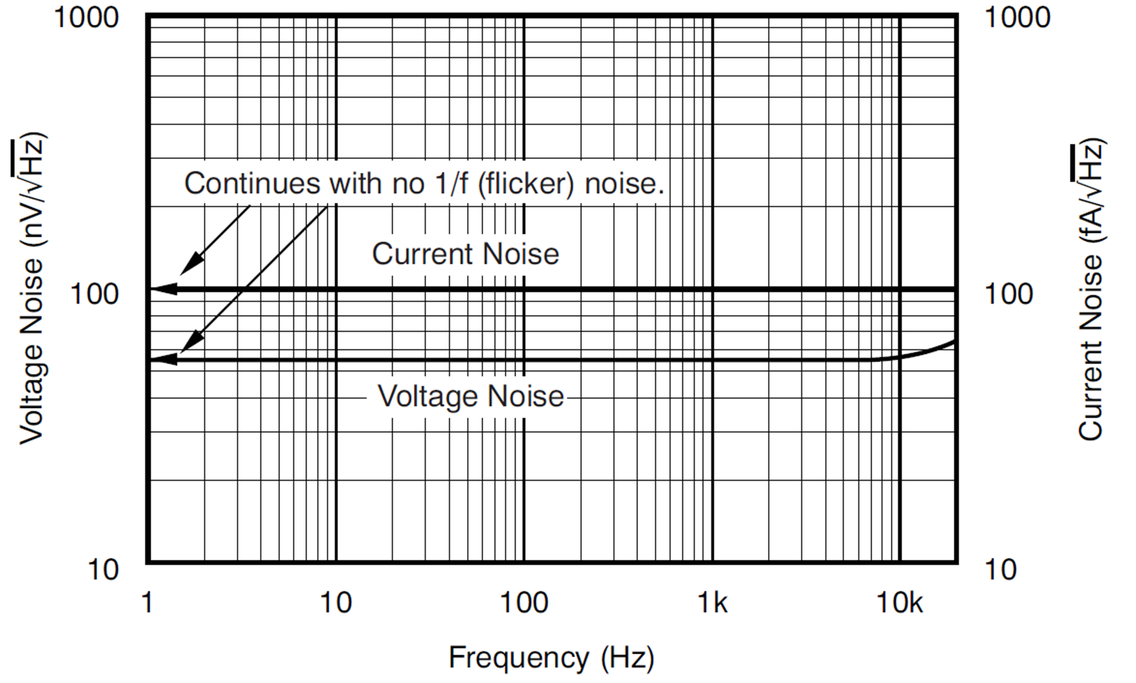
In Figure 2, the OPA333 current and voltage noise is flat from DC to 10 kHz. These two noise sources basically generate a DC offset voltage. The voltage noise curve immediately generates that DC offset, and the current noise generates a DC offset in combination with any circuit input resistance.
The low rms noise calculation for the auto-zero amplifier is the same as the broadband calculation (Equation 1).

Where VN-RMS is the rms noise across the frequency region
VCENTER is the noise at the center of the area under consideration
fMAX is the maximum frequency in the region
fMIN is the minimum frequency in the region
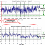
But let’s put this in a time-domain application space. Figure 3 shows the referred to input performance time measurement of the OPA333.
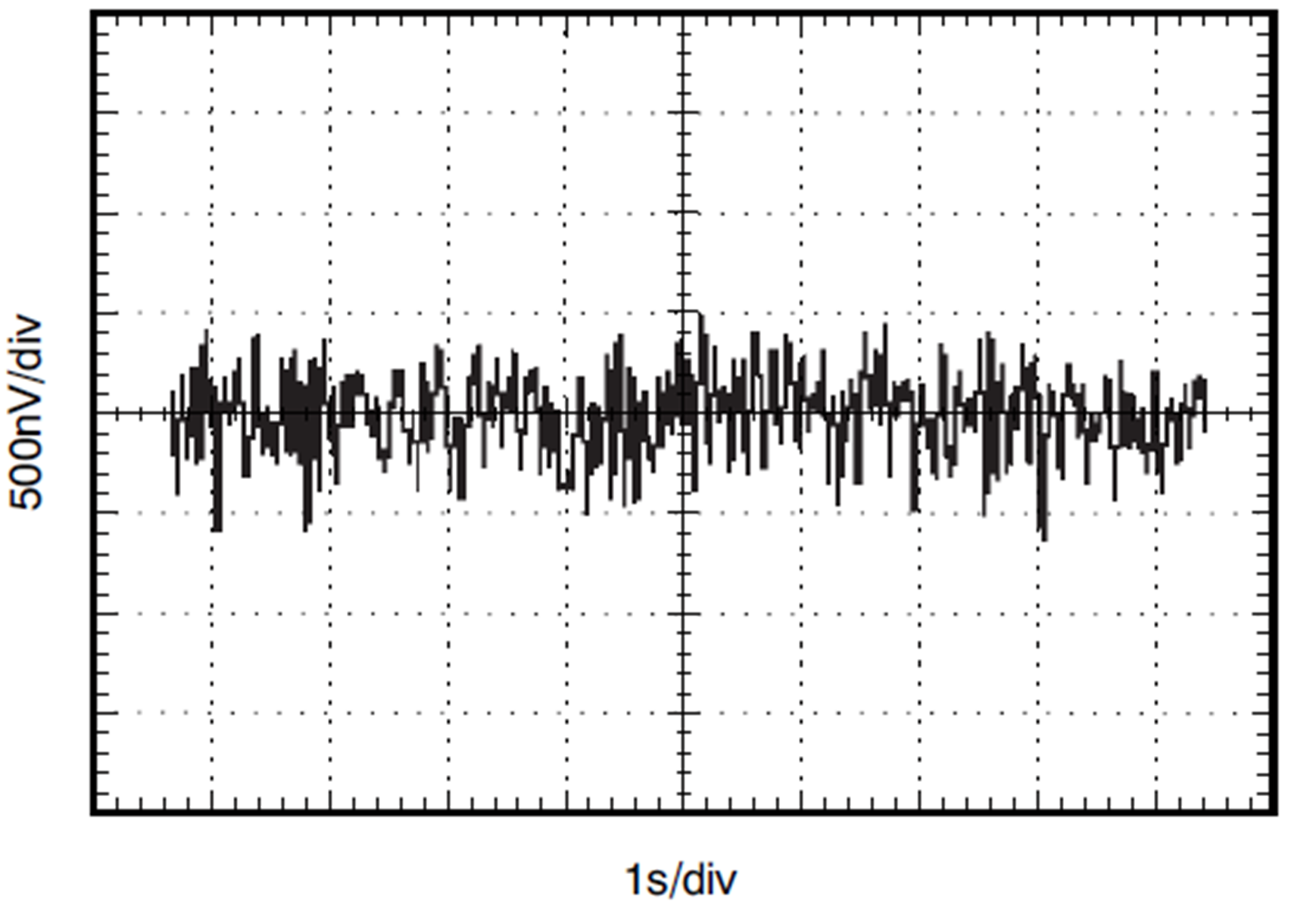
The peak-to-peak noise in Figure 3 is approximately ±500 nano-volts (nV) or averaging a constant 152nVrms or 1mVp-p offset voltage.
Because of the back-and-forth action with the auto-zeroing/chopping design approach, the input offset voltage, offset drift, peak-to-peak (p-p) noise of these amplifiers is much lower than the standard bipolar, FET, or CMOS input amplifiers. Let’s look at all the amplifiers that were in this 1/f series (Table 1).
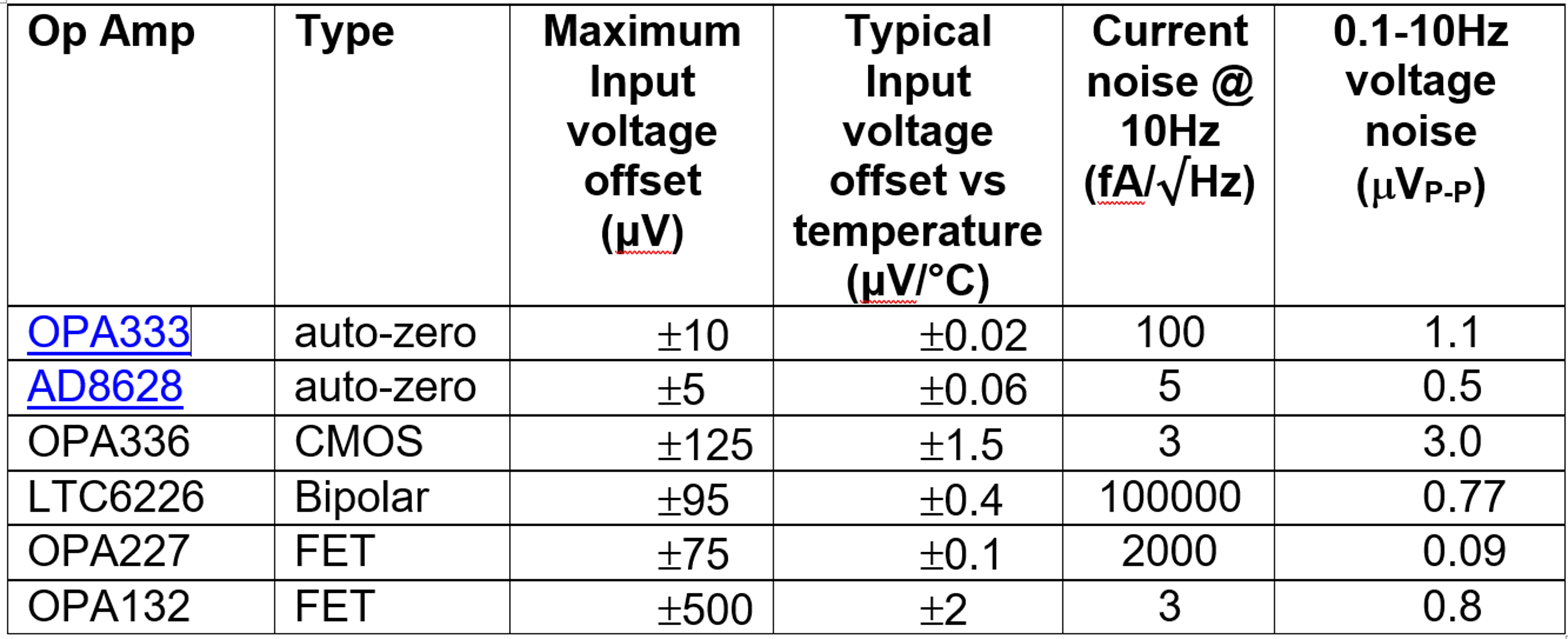
Table 1 has some hidden facts, such as the auto-zero amplifier noise is constant from DC to higher frequencies and the voltage noise translates into an amplifier DC offset voltage. Also, the bipolar current noise magnitude depends on the external input resistances.
What type of op-amp do you use?
Application circuits with low 1/f noise cater to DC measurement circuits. With this in mind, stick with the auto-zero amplifier and think about adding an analog or digital offset adjust circuit. You will be ahead of the game with the stable auto-zero amplifier, and if your system has a wide temperature range, the auto-zero amplifier is the real winner.
References
Noise Reduction Techniques in Electronic Systems, Henry W. Ott, John Wiley & Sons, ISBN 0-471-85068-3“
Ask the Applications Engineer – 39: Zero-Drift Operational Amplifiers”, Reza Moghimi, Analog Dialogue, March 2010 44,
“Understanding and Eliminating 1/f Noise”, Robert Kiely, Analog Dialogue 51-05, May 2017
“8.8 TI Precision Labs – Op Amps: Noise – 1/F flicker noise”, TI Precision Labs Video
“Op Amp Noise Relationships: 1/f Noise, RMS Noise, and Equivalent Noise Bandwidth”, MT-048 Tutorial, Analog Devices,
“Analysis and Measurement of Intrinsic Noise In Op Amp Circuits Part II: Introduction To Op Amp Noise”, Texas Instruments, Art Kay