Understanding the role and implications of impedance in RF transmission lines and antennas is vital to successful system performance.
The previous sections looked at the basics of impedance and VSWR. This section looks at the implications of VSWR measurements.
Q: Why should I care about reflected waves due to impedance mismatch and resultant non-unity VSWR?
A: There are several reasons why transmitter and amplifier outputs driving transmission lines and transmission lines driving antennas need to be concerned with VSWR:
- The standing waves can damage the output transistors (and even vacuum tubes!) of the transmitter.
- In systems with high voltage and current levels, the standing waves can damage a transmission line. The current maxima can induce local heating, which can distort or melt the plastics used, while the high voltages can cause arcing in some circumstances.
- Delays and signal distortion are likely since when a signal is reflected back towards the source, it can then be reflected back again towards the antenna. This can cause inter-symbol interference in data signals; in the old days of “analog” television, this was one of the causes of a “ghost” image seen on the screen (multipath was the other primary cause).
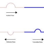
- The reflected signal represents lost power which is not reaching the load or antenna, although the loss is generally not as high as intuition might lead you to assume (Figure 1). Still, it is a loss, and every watt (or mW) and dB counts in many applications.
Q: When you say “not as high as intuition might lead you to assume” – can you be more specific?
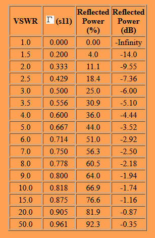
From the table, we see that a VSWR of 4 means that 36% of the power delivered by the source is reflected from the load, such as an antenna, while 64% of the power is delivered to the load. Note that a reflected power of 0 dB indicates all of the power is reflected (100%), while the VSWR would be infinite if all the power is reflected.
Also note that VSWR is a very non-linear function of the reflection coefficient Γ. There is very little difference in reflected power when the VSWR increases from 9 to 10; however, there is an 11% change in reflected power when the VSWR changes from 1 to 2.
Q: What VSWR values are acceptable in a design?
A: It largely depends on the application, of course. In general, a VSWR under 1.5:1 or 2:1 is acceptable (a perfect match yields a VSWR of 1:1). Always keep in mind that impedance of a given load, such as an antenna, is a function of frequency. A “wideband” antenna may have a nearly constant impedance as this VSWR across that wider band, while the impedance and this VSWR of a narrowband antenna so the VSWR will vary dramatically across the band of interest if that band is wide. Thus, the “flatness” of the impedance of a load such as an antenna must be compatible with the application bandwidth.
The next section looks at two major techniques for measuring impedance and VSWR.
Related EE World Content
What are the functions and principles of S-parameters (Part 1)?
What are the applications and measurements of S-parameters? (Part 2)
RF power amplifier, Part 1: Functions and Elements
Solar cells and power, Part 2 – power extraction
Measuring antenna properties
Using the Smith chart for Impedance matching, Part 1
Impedance matching and the Smith Chart, Part 2
The difference between SWR and TDR meters
Measure power in complex RF signals
What are RF waveguides? Part 1: context and principles
What are RF waveguides? Part 2: implementation and components
References
- Wikipedia, “Maximum power transfer theory”
- Tutorials Point, “Maximum Power Transfer Theorem”
- Microwaves 101, “Why Fifty Ohms?”
- Belden, “50 Ohms: The Forgotten Impedance”
- High Frequency Electronics, “There’s Nothing Magic About 50 Ohms”
- Wilson Amplifiers, “50 Ohm vs. 75 Ohm: Which is Best For You?”
- Wikipedia, “Standing wave ratio”
- Antenna-Theory, “VSWR (Voltage Standing Wave Ratio)”
- Electronics Notes, “What is VSWR: Voltage Standing Wave Ratio”
- Electronics Notes, “How to Measure VSWR: approaches & test instruments”
- Maxim Integrated Products, “Glossary Definition for impedance-matching”
- Maxim Integrated Products, “Glossary Definition for VSWR”
- Nuts and Volts, “Impedance Matching”
- Mini-Circuits, “Impedance Matching Devices”
- Mini-Circuits, “Demystifying Transformers: Baluns and Ununs”
- NI (National Instruments), “Impedance and Impedance Matching”
- Tektronix, “Introduction to VNA Basics”
- Triad Magnetics. “Understanding the Maximum Power Theorem”
- QSL Net, “50 MHz (6 Meter) Tuner Circuits”
- QSL Net, “Six Meter Transmatch (Tuner)”
- M0UKD (Amateur Radio Personal Site), “End Fed Half Wave Antenna Coupler (EFHW)”
- Altium Limited, “Stripline vs Microstrip: PCB Routing Differences and Guidelines”
- Researchgate, “A Self-Complementary 1.2 to 40 GHz Spiral Antenna with Impedance Matching”