Understanding the role and implications of impedance in RF transmission lines and antennas is vital to successful system performance.
The previous section looked at the basics of VSWR. This section looks at two approaches to measuring impedance and VSWR.
Q: What do engineers and users need to know?
A: For some applications, such as connecting a transmitter to an antenna, it is often enough to know just the VSWR. Other applications which involve interfacing one RF section of a smartphone to another may need to know the actual impedance.
Q: What’s the easiest way to measure VSWR?
A: The basis of a VSWR meter is the directional coupler (Figure 1). This approach samples a small amount of power in one direction and then uses a diode to rectify this, after which it is applied to a meter. Two couplers are used, either one for each direction or just one can be used and be switched between directions.
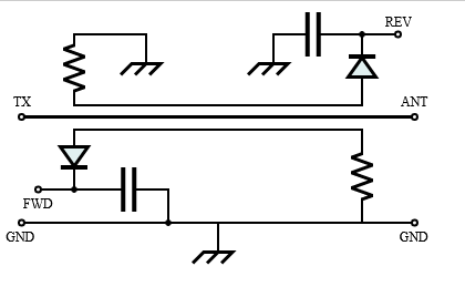
Q: Then what happens?
A: The coupler then implements a “calculation” which yields the VSWR number; this calculation can be done using all-analog circuitry or via more complicated A/D converters and a processor executing math algorithms. The all-analog approach is very effective and cost-effective. Directional couplers are frequency sensitive, so the VSWR meter must operate on the frequencies that are needed.
Q: When and where is this directional coupler used?
A: There are two approaches:
- VSWR measurements made using power from the transmitter. These are usually made with a transmitter operating at a reasonable level of power. These VSWR meters often stay in the line during normal operation to monitor current readings to indicate a change in conditions or a fault.
- Using a test instrument and supplying a low-power stimulus to the load or system. This type of VSWR measurement is normally done during set-up or development but only as needed. The meter cannot be left in the circuit during normal operation of the transmitter,
Q: What’s the limit of the basic SWR meter?
A: An SWR meter does not measure the actual impedance of a load (the resistance and reactance) but only the mismatch ratio. The SWR meter’s impedance must also match the line’s impedance (typically 50 or 75 ohms), so some SWR meters have switches or adapters that select or match the impedance.
Q: What’s a typical directional-coupler VSWR meter look like?
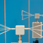
A: The Bird 43 Wattmeter is a widely used, basic insertion-type instrument designed to measure both forward and reflected power in coaxial transmission lines under any load condition (Figure 2). It can be left in the line for continuous monitoring of either the transmitter power output or the amount reflected by the antenna. It has full-scale accuracy of ± 5%, quick-change connectors, and a full range of plug-in elements (modules) to provide a wide choice of frequency ranges (450 kHz to 2.7 GHz) and power levels (100 mW to 10 kW).

Q: What’s the other instrument and technique?
A: A vector network analyzer can provide magnitude and phase characteristics of the active or passive device under test (DUT), providing complete device characterization.
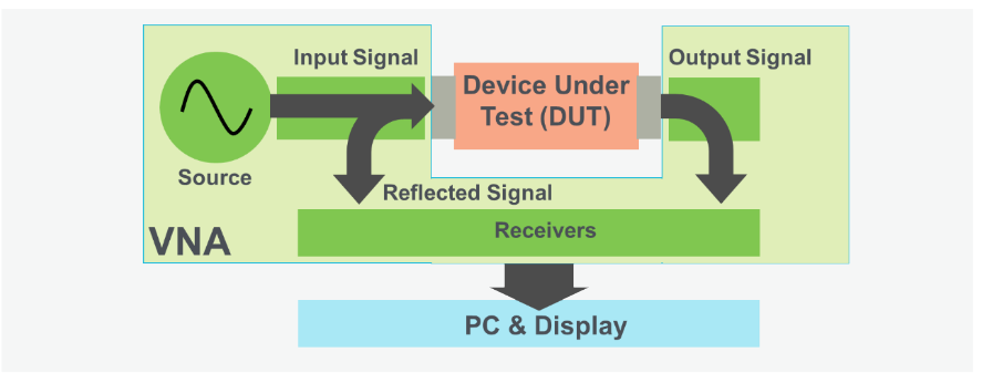
Q: What does the VNA do?
A: The VNA contains a source that generates a known stimulus signal, and one or more receivers assess changes to this stimulus caused by the DUT (Figure 3). The stimulus signal is injected into the DUT and the VNA measures both the signal reflected from the input side and the signal that passes through to the output side of the DUT. The VNA’s receivers measure the resulting signals and compare them to the known stimulus signal.
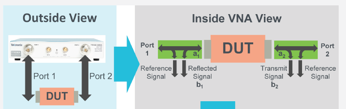
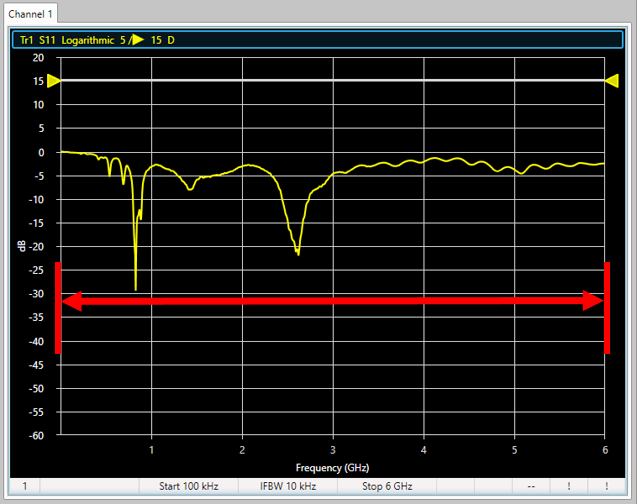
The resulting data can be displayed as magnitude and phase graph, plotted on a Smith chart, or S11 S-parameter (Figure 4).
This is just a brief overview of making VSWR measurements and instrumentation; it is both a simple and extremely complicated subject. The next section looks at a few examples of devising and implementing matching circuits.
Related EE World Content
What are the functions and principles of S-parameters (Part 1)?
What are the applications and measurements of S-parameters? (Part 2)
RF power amplifier, Part 1: Functions and Elements
Solar cells and power, Part 2 – power extraction
Measuring antenna properties
Using the Smith chart for Impedance matching, Part 1
Impedance matching and the Smith Chart, Part 2
The difference between SWR and TDR meters
Measure power in complex RF signals
What are RF waveguides? Part 1: context and principles
What are RF waveguides? Part 2: implementation and components
References
- Wikipedia, “Maximum power transfer theory”
- Tutorials Point, “Maximum Power Transfer Theorem”
- Microwaves 101, “Why Fifty Ohms?”
- Belden, “50 Ohms: The Forgotten Impedance”
- High Frequency Electronics, “There’s Nothing Magic About 50 Ohms”
- Wilson Amplifiers, “50 Ohm vs. 75 Ohm: Which is Best For You?”
- Wikipedia, “Standing wave ratio”
- Antenna-Theory, “VSWR (Voltage Standing Wave Ratio)”
- Electronics Notes, “What is VSWR: Voltage Standing Wave Ratio”
- Electronics Notes, “How to Measure VSWR: approaches & test instruments”
- Maxim Integrated Products, “Glossary Definition for impedance-matching”
- Maxim Integrated Products, “Glossary Definition for VSWR”
- Nuts and Volts, “Impedance Matching”
- Mini-Circuits, “Impedance Matching Devices”
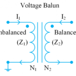
- Mini-Circuits, “Demystifying Transformers: Baluns and Ununs”
- NI (National Instruments), “Impedance and Impedance Matching”
- Tektronix, “Introduction to VNA Basics”
- Triad Magnetics. “Understanding the Maximum Power Theorem”
- QSL Net, “50 MHz (6 Meter) Tuner Circuits”
- QSL Net, “Six Meter Transmatch (Tuner)”
- M0UKD (Amateur Radio Personal Site), “End Fed Half Wave Antenna Coupler (EFHW)”
- Altium Limited, “Stripline vs Microstrip: PCB Routing Differences and Guidelines”
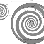
- Researchgate, “A Self-Complementary 1.2 to 40 GHz Spiral Antenna with Impedance Matching”