Attenuators are often defined as electronic devices that reduce the power of a signal without introducing significant distortion. While that’s not incorrect, it’s also not complete. For example, optical attenuators can be based on fixed or variable neutral density (ND) filters and are largely mechanical constructions.
This FAQ considers basic types of electronic attenuators. Other FAQs in this series consider optical attenuators and loopbacks, the specialized cryo attenuators designed for quantum computers, and the similarities and differences between attenuators and filters.
There are several ways to classify attenuators. Whether they are fixed, programmable or variable, or designed to handle low or high power levels. They can be classified by package style, and there’s a distinction between audio attenuators and L pads and between RF attenuators and limiters.
The most common function of attenuators is to protect sensitive RF circuitry from high signal levels. But that’s not their only use. Attenuators can also be placed between reflective components to limit the development of standing waves that might otherwise build up. They are also used in testing equipment to protect sensitive circuits from high power levels and to extend the ranges of RF amplifiers or RF power meters.
Basic RF attenuator topologies include T pads and pi (π) pads. Depending on the application, they can be balanced or unbalanced networks. RF attenuators used with coax lines are generally unbalanced forms while attenuators used in lower frequency designs with twisted pair lines are usually balanced forms. Attenuators are dissipative devices and reduce the power level by absorbing RF energy and converting it into heat. Since they don’t reflect RF energy, attenuators can also be used to reduce reflected signals.
By lowering the standing wave ratio (SWR), fixed attenuators can be used in impedance matching applications. For example, the output impedance of a power amplifier may not be optimal for driving a 50 ohm load, resulting in an increased in reflections and loss of signal power. The voltage standing wave ratio (VSWR) measures the reflections caused by impedance mismatches. Placing a fixed attenuator before the amplifier will increase the return loss and improve the VSWR since VSWR is inversely proportional to return loss.
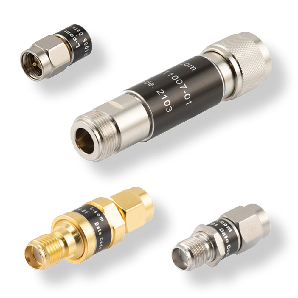
Basic RF attenuators are rated for up to 2 or 3 watts of power and are available in a range of coax cable configurations such as SMA and Type N connectors and are typically rated for frequencies from DC to 18 GHz (Figure 1).
Applications that need to maintain a specified insertion loss often use computer-controlled programmable attenuators, also called active variable attenuators. The use of computer control makes programmable attenuators especially useful in automatic test equipment and simulation environments. In addition, variable attenuators are used to control a signal level and keep it within a required range. They are sometimes used for modulation in quadrature amplitude modulated (QAM) or amplitude modulated (AM) communication systems.
Step attenuators and variable attenuators are like programmable attenuators, but these designs are manually controlled and are used in specialized test equipment in laboratory and engineering design environments. They are forms of passive attenuators and can introduce a fixed or variable level of attenuation. Some provide attenuation in a series of switchable steps.
DC blocking attenuators are specialized devices designed for use in testing and other environments that benefit from DC isolation. Directional attenuators operate in one direction and are designed for the RF signal to go only from the input to the output. Bidirectional attenuators are more common and can have the signal travel in either direction.
What’s a high-power RF attenuator?
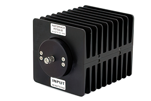
That depends on the application and operating frequency. At frequencies of a few MHz or lower, attenuators may be required to handle hundreds or even thousands of watts. At GHz frequencies, tens of watts are often considered high power (Figure 2). That difference arises for several reasons. First, RF losses tend to increase as the frequency increases. And at high frequencies, conductors and dielectrics are smaller and closer spaced, limiting the power dissipation possibilities.
Thermal management is an important consideration for high power attenuators. Since all attenuators work by absorbing RF energy, the temperature of the attenuator increases as more energy is absorbed. At higher operating temperatures, the attenuation can be significantly lower compared to room temperature. Reduced attenuation can result in signals passing through the attenuator that are powerful enough to damage downstream devices.
While most power RF attenuators are air cooled, there are also water-cooled, oil-dielectric, convection cooled, and conduction cooled designs. For example, one 4 kW 30 dB attenuator is available with a T pad construction using carbon-film-on-ceramic cylindrical resistors immersed in an oil dielectric coolant. The attenuation is specified to ±0.5 dB and calibration data is supplied for 30, 100, 200, 300, 400, and 500 MHz, which is accurate to ±0.2 dB.
Audio attenuators and L pads
The much lower frequencies of audio signals compared with RF signals makes it possible to use simpler attenuators called ‘L pads’ in audio systems. An L pad is a network composed of two impedances compared with the more complex pi pad and T pad designs of RF attenuators. In addition to providing signal attenuation, L pads are used for impedance matching. Their use is limited to audio systems largely because L pads are lossy, too lossy for practical use in RF signal chains.
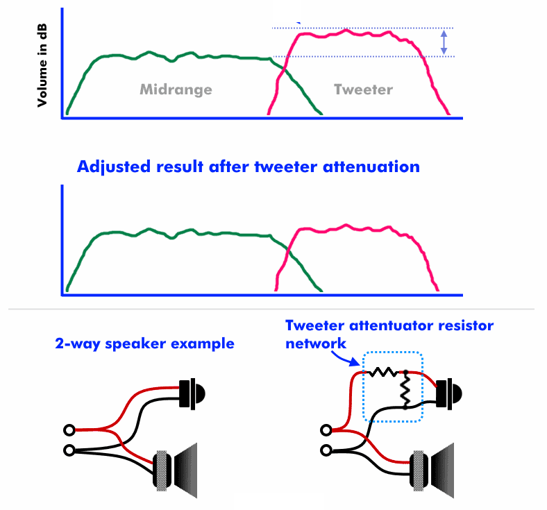
In audio systems, smaller speakers tend to be more efficient compared with larger, and lower frequency, speakers. At a given amplifier power output, small speakers like tweeters can sound louder compared to midrange speakers or low frequency woofers. Inserting an L pad into the tweeter circuit can reduce the dB output of the speaker while maintaining impedance matching with the amplifier (Figure 3). Depending on the audio system design, a line level attenuator can be used in the preamp stage, or a power attenuator can be used after the power amplifier. A line level solution may be rated for 0.5 W while a power L pad attenuator may be rated for 10 W or more. Amplifier design and speaker selection are among the factors that determine the optimal choice.
When to limit and when to attenuate?
Like attenuators, limiters can be used to reduce the power of an RF signal and protect sensitive components. Limiters reduce signal power if it exceeds the threshold of the limiter. Limiters are often used to protect sensitive signal conditioning circuitry like low noise amplifiers (LNAs) and receivers from a high signal level that could result in damage or reduced performance levels. Limiters can be found in a range of RF signal chain applications.
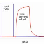
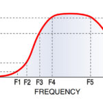
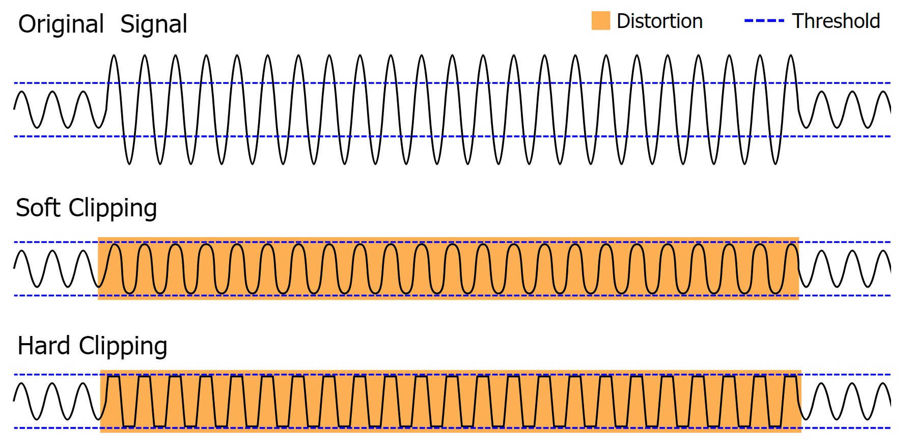
RF limiters are often implemented with PIN diodes and function as incident power-controlled variable impedance devices whose attenuation is a function of the incident signal power. Below the designed threshold level, limiters exhibit minimal attenuation. Once the threshold has been reached, the limiter attenuates the peaks of stronger signals. In extreme circumstances, limiters can clip the incoming signal. Depending on the design, RF limiters can implement soft clipping where the basic waveform is maintained, or hard clipping that literally chops off the extremes of the waveform (Figure 4).
Summary
RF attenuators are available that deliver a variety of functions including fixed, programmable, variable, step, and DC blocking. In addition, power RF attenuators are available that can handle multiple kW of power. RF attenuators tend to be T pads and pi (π) pads with low power dissipations, and they can be balanced or unbalanced. Audio attenuators, L pads, are simpler and more dissipative designs. In some applications, RF limiters based on PIN diodes can be used instead of RF attenuators.
References
4kw, Oil-Cooled RF Attenuator, Bird RF
Attenuator, Wikipedia
Difference Between RF Limiters and Attenuators, Pasternack
L Pad Calculator + Speaker Attenuation Guide, SoundCertified
Limiter, Wikipedia