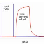
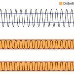
Quantum computers are cryogenically cooled because their quantum bits (qubits) are extremely delicate and sensitive to disruptions from even minute amounts of thermal noise, such as Johnson-Nyquist (J-N) noise. J-N noise is generated by the thermal agitation of electrons, regardless of any applied voltage, when the conductor is at equilibrium. Even small amounts of J-N noise can disrupt qubits and act as a limiting factor on quantum computer performance. Operation at cryogenic temperatures can minimize J-N and other noise sources but is insufficient to eliminate all noise sources. That’s where cryo attenuators come in.
Cryo attenuators are used on the drive lines in quantum computers to eliminate, as much as possible, J-N and other noise sources. Establishing a communication and control link between the coldest level in a quantum computer and the outside world creates numerous opportunities for noise to creep into the system. In fact, a typical cryogenic refrigeration system for a quantum computer can include thousands of cryo attenuators, many of which are tested for operation down to 4 milliKelvins (mK).
Fabricating large numbers of qubits on a single chip and cooling them down to mK temperatures is relatively simple compared with linking them into a useful computational system. Heat load management and thermal noise minimization are key challenges. The dilution fridges used to create the cryogenic temperature needed for qubit operation are multistage devices. A standard design can have five cooling levels below room temperature (RT). The introduction of thermal noise into the RF and DC cables and other microwave components at any stage limits the number of qubits that the fridge can support. The thermal stages include (Figure 1):
- 50K, where the goal is to move the temperature toward 35K
- 4K, where the temperature approaches 3K
- Still, which reaches about 1K
- Cold plate (CP) where the temperature is about 100 mK
- The mixing chamber (MXC), where the qubits reside at about 10 mK

The multiple cooling stages in a dilution fridge are connected with numerous (in some cases, thousands) of RF and microwave cables that are long enough to create thermal management (i.e., thermal noise) issues. In some designs, thousands of coaxial cryo attenuators are needed to remove all traces of thermal noise. The fact that attenuators tend to be thermally dissipative devices increases the challenges associated with integrating them into quantum computer environments. Compared with conventional attenuators, cryo attenuators are specially designed to minimize self-heating and for reliable operation at temperatures down to 4 mK.
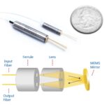
Another possible solution to the thermal noise problem is to replace the microwave cabling with fiber optic interconnects. Fiber optics is potentially attractive because the optical fibers have much lower thermal conductivity (carry less noise) than microwave coax cables. The fiber optic cables have enough capacity to support multiple links over a single fiber using wavelength division multiplexing, promising simpler system designs.
In fact, researchers with the National Institute for Standards and Technology (NIST) reported in the journal “Nature” a demonstration of a fiber optic qubit control system by putting a photodiode with a supercooled qubit in the MXC stage of a dilution fridge. While the experiment was a success, it is not scalable with current technology. The cooling power of the MXC stage was only 20 μW, and the active power dissipation from the optical to microwave conversion in the fiber optic link is too high for there to be more than a single fiber-connected qubit in the MXC stage.
So, large numbers of cryo attenuators will be needed to build quantum computers for the foreseeable future. In terms of a lumped-element circuit model for a T-pad attenuator, a cryo attenuator looks basically like a conventional microwave attenuator. The keys are in the materials and geometries used to fabricate cryo attenuators.
Figure 2 shows the structure of a single 10 dB cryo attenuator cell. The nickel-chromium (NiCr) resistors are 75 nm thick. NiCr is used because it maintains its properties as a resistor even at 4 mK and does not become a conductor. The resistors are connected using a 1 μm thick silver film in a coplanar waveguide geometry with a center conductor width (wc) = 0.8 mm and gap width (wg) = 0.26 mm on a 0.5 mm thick quartz substrate. The resulting cryo attenuator operates from 1 to 10 GHz. The 75 nm thick NiCr dissipative layer uses the 1 μm thick silver films as hot electron heat sinks.

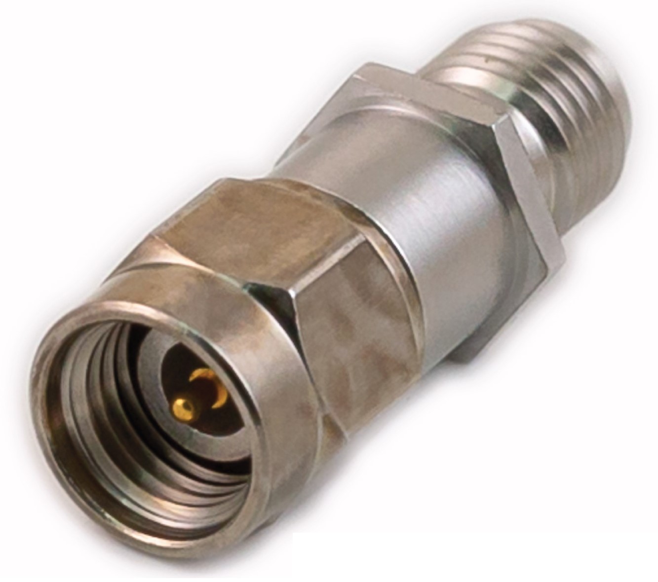
Commercial cryo attenuators are available that are optimized for use in multiple stages to combat thermal noise in dilution fridges used for quantum computers. These axial attenuators have a mechanical design that minimizes self-heating enabling thermally quiet attenuations at mK temperatures. They are available with attenuation values of 0, 3, 6, 10, and 20 dB and are rated for up to 2 W of power. When using a 2.92 mm connector, they are rated from DC to 40 GHz (Figure 3). Using smaller SMA or SMPM connectors reduces the frequency rating to DC to 18 GHz. They are fabricated with a proprietary thin film resistor material connected using gold-plated beryllium copper conductors and rated for temperatures as low as 20 mK.
Bulkhead cryo attenuators
Axial cryo attenuators are a common solution to managing J-N and other noise sources in quantum computers. The increasing number of qubits in quantum computers means more RF lines. A larger dilution fridge is needed if the number of RF lines increases too much. But making larger and larger dilution fridges is a challenge of its own. One solution is to replace 2.92 mm connectors in axial attenuators with smaller SMP and SMPM connector designs. But that can limit the operating frequency.
Some quantum computer designs can benefit by replacing axial attenuators with bulkhead-style cryo attenuators. Bulkhead cryo attenuators eliminate the need for RF connectors within the dilution fridge chill plates and reduce the number of contact points, simplifying thermal and noise management. Reducing the number of contact points also reduces the overall parts count and can simplify quantum computer assembly.
Like their axial counterparts, bulkhead cryo attenuators use oxygen-free high thermal conductivity (OFHC) copper and NiCr resistors on a thermally conductive quartz dielectric that supports minimal change in attenuation over temperature changes. The resistors have a temperature coefficient of resistance (TCR) of less than 15 ppm/°C. These attenuators are available in several bands from DC to 40 GHz and are in 8, 16, and 24 port configurations with attenuations up to 20 dB. For example, a 16-channel form factor is available with a 2.54 mm pitch, signal to signal, that can enable highly compact solutions (Figure 4).

Summary
Quantum computers promise to revolutionize many areas of science, communications, medicine, and engineering. For the qubits in quantum computers to function, they must be shielded entirely from J-N and other noise sources. The use of cryo attenuators will be an important element in enabling the development of advanced quantum computers. Those attenuators are fabricated using specific materials with precise geometries and are available in axial and bulkhead configurations. Thousands of attenuators can be required to support the entire dilution fridge cold chain from the 35 K temperatures at the top to the 10 mK temperatures in the MXC stage where the qubits reside.
References
Cryo Attenuators for Quantum Computing, apitech
Cryo Attenuators for Quantum Computers, Heynen
Control and readout of a superconducting qubit using a photonic link, Nature
Engineering cryogenic setups for 100-qubit scale superconducting circuit systems, EPJ Quantum Technology
Engineering the microwave to infrared noise photon flux for superconducting quantum systems, EPJ Quantum Technology
Ganged Coaxial Attenuator, Ardent Concepts
Johnson–Nyquist noise, WikipediaMicrowave attenuators for use with quantum devices below 100 mK, Journal of Applied Physics
Scaling up Superconducting Quantum Computers with Cryogenic RF-photonics, Arvix