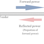
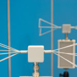
Standard filters reflect unwanted stopband energy, but reflectionless filters present a seamless impedance across both stopband and passband which greatly improves performance of the RF signal chain.
Filters are an inherent, inescapable, necessary component in electrical and electronic circuits. Modern systems would be impractical and likely impossible without filters, whether at low frequencies down to DC or into the tens of gigahertz range.
For some engineers, filters are something to know as little about as possible: just find a suitable available one and drop it in, or a “cookbook” design that can be copied. For others, it’s important to understand the math behind the filter but only as much (or little) as needed to design, make, or buy a good one. For a smaller but important cluster of filter enthusiasts, there’s the sheer delight in the math – which can get fairly intense, no doubt about it – that defines all aspects of both theory and even deviations in practical realizations. These differences exist regardless of the filter topologies, and analog (continuous-time) and digital (discrete- or sampled-time) filters; the latter are viable only up to a few hundred kilohertz or low megahertz frequencies to the computation requirements involved.
At the lower frequencies, digital filters offer a new range of options that analog ones cannot. In addition to the IIR (infinite impulse response) class of filter for which there is an analog equivalent, there is the FIR (finite impulse response) digital filter which can be programmed but for which there is no analog equivalent and so cannot be built with physical components. At the other end of the spectrum, filters for the gigahertz and above range generally cannot use discrete lumped components since the required devices are too small to be practical, and parasitics easily overwhelm nominal specifications. Thus, new types of filters based on surface acoustic wave (SAW) and bulk acoustic wave (BAW) ceramic structures are needed, as well precisely dimensioned circuit-board layouts.
The often-ignored filter characteristic
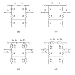
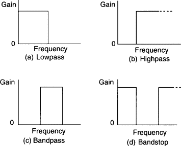
Still, one aspect of filters is easily and often ignored or about which the user doesn’t think much, if at all. The primary function of most filters, regardless of type (bandpass, low pass, high pass, notch/bandstop (Figure 1), is to pass energy at some specified frequencies (passband) and to attenuate (block) it at others (stopband). (There is one important exception: filters whose role is to pass all frequencies but shift the phase of some or all frequency components; they are an entirely different story.)
The question is: what happens to the energy which the filter stops or attenuates? The answer is simple: it depends. For lower-frequency filters such as those which eliminate 50/60 Hz interference or attenuate adjacent channels in kilohertz-band signals, that energy (and associated power) is mostly converted to heat. In most cases, the signal levels are low, and the amount of energy and power in the stopband is minor or modest, so the heating effect is also negligible. However, the energy is substantial for some power-related filters, as is the heat, so the filter components must be rated to handle and dissipate that power.
The stopband dissipation situation is different at higher frequencies, starting into the hundreds of megahertz and gigahertz. We will explore this in Part 2.
EE World References
- VSWR and impedance, Part 6: Microstrip and stripline
- VSWR and impedance, Part 5: Making a match
- VSWR and impedance, Part 4: Measurements
- VSWR and impedance, Part 3: Implications
- VSWR and impedance, Part 2: Reflected power
- The basics of VSWR and impedance, Part 1
- What’s all this VNA calibration stuff?
- BAW filters keep RF interference out
- An overview of filters and their parameters, Part 4: Time and phase issues
- An overview of filters and their parameters, Part 3: Key parameters
- An overview of filters and their parameters, Part 2: Basic concepts
- An overview of filters and their parameters, Part 1: Context
- Filters, Part 1: Analog, switched, and digital filters
- Filters, Part 2: SAW and BAW devices for RF.
- 5G RF filters need more innovation
External References
- Mini-Circuits, “Reflectionless Filter Basics: A Brief History of the Genesis of Reflectionless Filters”
- Mini-Circuits, “Filtering without Reflections: Flattening Multiplier Chain Conversion Efficiency & More“
- Mini-Circuits, X-Series MMC DC to 21 GHz Reflectionless Filters ddatasheetMatthew Morgan, 2015,“Synthesis of a New Class of Reflectionless Filter Prototypes”
- Morgan, Groves, and Boyd, 2018, “Reflectionless Filter Topologies Supporting Arbitrary Ladder Prototypes”
- Microwaves 101, “Reflectionless filters”
- Microwave Journal, “Reflectionless Filters Improve Linearity and Dynamic Range”
- Matthew Morgan, U.S. Patent 8,392.495 B2 (2013), “Reflectionless filters”
- Matthew Morgan, U.S. Patent 10,277,189 B2(2019), ”Transmission line reflectionless filters”